Based on the plots of Vin and Vout, is the op-amp consistent with its inverting function? Justify your answer.
Based on the plots of Vin and Vout, is the op-amp consistent with its inverting function? Justify your answer.

Power System Analysis and Design (MindTap Course List)
6th Edition
ISBN:9781305632134
Author:J. Duncan Glover, Thomas Overbye, Mulukutla S. Sarma
Publisher:J. Duncan Glover, Thomas Overbye, Mulukutla S. Sarma
Chapter6: Power Flows
Section: Chapter Questions
Problem 6.61P

Related questions
Question
Based on the plots of Vin and Vout, is the op-amp consistent with its inverting function? Justify your answer.
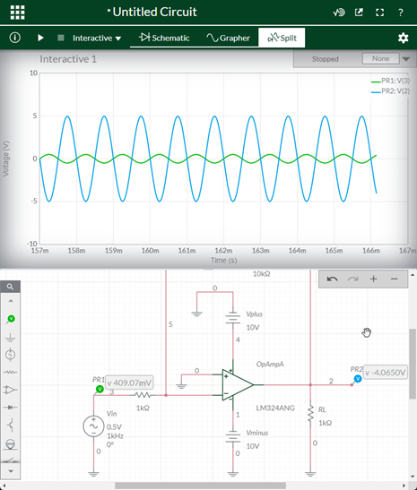
Transcribed Image Text:•Untitled Circuit
schematic
Grapher
Split
Interactive
Interactive 1
Stopped
None
10
-PR1: V(3)
-PR2: V(2)
-10
157m
158m
159m
160m
161m
162m
163m
164m
165m
166m
167m
Time (s)
10kQ
Vplus
10V
4
OpAmpA
PR2
v -4.0650V
PR1
v 409.07mV
2
1kQ
LM324ANG
RL
Vin
10.5V
1kHz
0°
Vminus
10V
Q O A YO
W abeon
Expert Solution
This question has been solved!
Explore an expertly crafted, step-by-step solution for a thorough understanding of key concepts.

Step by step
Solved in 2 steps with 2 images

Knowledge Booster


Learn more about
Need a deep-dive on the concept behind this application? Look no further. Learn more about this topic, electrical-engineering and related others by exploring similar questions and additional content below.Recommended textbooks for you
Power System Analysis and Design (MindTap Course …
Electrical Engineering
ISBN:
9781305632134
Author:
J. Duncan Glover, Thomas Overbye, Mulukutla S. Sarma
Publisher:
Cengage Learning
Power System Analysis and Design (MindTap Course …
Electrical Engineering
ISBN:
9781305632134
Author:
J. Duncan Glover, Thomas Overbye, Mulukutla S. Sarma
Publisher:
Cengage Learning