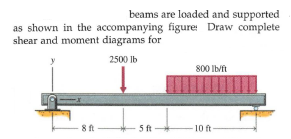
beams are loaded and supported as shown in the accompanying figure: Draw complete shear and moment diagrams for 2500 lb 800 Ib/ft 8 ft 5 ft 10 ft


Q: 1500 Ib/ft В A C 6000 lb – 4 ft → - 6 ft – Figure - 02
A: Let RA and RB are reactions at A and B Using equilibrium of forces in vertical and moment at A is…
Q: Question # 1: Draw shear force and bending moment diagrams for the beam shown in Figure below.…
A:
Q: When loads and moments are applied to the cantilever beam as shown in the picture below, draw the…
A:
Q: 2: Draw the shear and bending moment diagrams for the beam shown. For your explanation section, you…
A:
Q: Draw shear force digam and bending moment digram for the following beam 2.0 kips / ft A В 15.0 ft…
A: Let RA and RB are reactions at A and B By using law of equilibrium RA+RB =12 Moment at point A is…
Q: 6.. A cantilever beam is 2.5 m long, and carries a concentrated load of 380 N at its midpoint, and…
A:
Q: Draw the shear and moment diagrams for each beam shown in figure:
A:
Q: The simple beam AB, shown below, supports a concentrated load of 22 kN and a segment of a…
A:
Q: Problem 1. Write shear and moment equations for the beam loaded as shown in figure below. Also, draw…
A:
Q: For the beam shown in the figure, draw the shear and moment diagrams using the area method. Show all…
A:
Q: whose centre lines are 10 m above A. The piles are spaced 1 m apart between centres and the depth of…
A:
Q: PROBLEM#4 WRITE SHEAR AND MOMENT EQUATIONS FOR THE BEAMS IN THE FOLLOWING FIGURE IN EACH SEGMENT,…
A:
Q: QB/ For a simple beam loaded as shown in Figure below. Write shear and moment equations for the beam…
A:
Q: Draw complete shear and bending moment diagrams for the beam pictured below:
A: The free-body diagram of the given beam can be drawn as below, Here RB and RC are the reactions at…
Q: PS. 2. Sketch the shear and bending moment diagrams for the beams below, indicating values of shear…
A:
Q: B: For the simply supported beam shown in the figure, write equations for the shearing force and…
A:
Q: A beam is loaded and supported as shown in Fig. Using the coordinate axes shown, write equations for…
A: Given Data: The load per unit length is w = 500 lb/ft. The moment acting on the beam is M0 = 6000…
Q: Wo A
A: Let RA and RB are the reactions at the supports A and B respectively. Apply +↺∑Mat A= 0 in the…
Q: . For the beam shown, calculate (a) the maximum bending stress; and (b) the bending stress at a…
A:
Q: Draw the shear(V) and moment(M) diagrams for the overhang beam given below.
A:
Q: 7.0 kN/m 4m 16 m
A: given; ⇒reaction force at A=RA⇒reaction force at B=RB⇒load intensity (w)=7KN/m⇒AC=16m⇒BC=4m
Q: beams are loaded and supported as shown in the accompanying figure: Draw complete shear and moment…
A: The free-body diagram of the given beam is as shown below - since there is only point load acting…
Q: Draw the shear and moment diagrams for each beam shown in figure:
A:
Q: A beam 12 m is simply and symmetrically supported over a span of 8 m. it carrier concentrated loads…
A: For solution refer below images.
Q: For the simply supported beam shown in the figure, write equations for the shearing force and…
A:
Q: Draw the complete shearing force and bending moment diagrams for the 1. beam shown below. State the…
A:
Q: "Draw the shear and moment diagrams or the beams shown in the figure below
A:
Q: Problem 2. The overhanging beam ABC in figure carries a concentrated load and a uniformly…
A: Given: AB= 4 ft BC= 10 ft Uniform load on BC=120 lb/ft Load at A=200lb To find:- To draw shear force…
Q: Draw the shear and moment diagrams for each beam shown in figure
A: According to the details provided in the question we need to draw SFD bmd diagram
Q: Write shear and moment equations for the beam loaded as shown in figure below. Also, draw shear and…
A:
Q: B: 10 KN/m For the simply supported beam shown in the figure, write equations for the shearing force…
A:
Q: For the beams shown in Figure 3.5, draw the shear diagrams and note all critical values for shear.…
A: An equivalent load of uniformly distributed load refers to the single load which can be used to…
Q: The overhanging beam ABC in figure carries a concentrated load and a uniformly distributed load.…
A:
Q: Use the graphical method to construct the shearforce and bending-moment diagrams for the beams shown…
A:
Q: Compute the shear and moment diagram of the given figure below. Show complete values in the…
A: TO find Shear and moment diagram
Q: Calculate the bending moment at points A and B for the beam shown below.
A:
Q: For the simply supported beam subjected to the loads shown. Let a=3.00 m, b=4.00 m, PB = 30kN, and…
A:
Q: Draw shear force and bending moment diagrams for a cantilever beam AB carrying a concentrated load W
A:
Q: A 6-m simply supported beam AB supports a trapezoidal distributed load. The intensity of the load…
A:
Q: A cantilever beam of length 2 m carries the point loads as shown in Fig 2. Draw the shear force and…
A:
Q: Draw the shear and bending-moment diagrams for the beam and loading shown following figures:
A:
Q: Q3: Draw the shear force and bending moment diagrams for the loaded beam (shown (see figure below).…
A:
Q: Determine the shear and moment equations for the beam shown in the figure. Also, draw the shear and…
A: To find: Shear and moment equations. Shear force diagram Bending moment diagram
Q: Draw complete shear force and bending moment diagrams for the beam. Label all graphs with the…
A: Shear force Shear force is a force which is acting parallel to the cross section of the beam.…
Q: Draw a complete shearing force and a bending moment diagram for the for the beam shown in the…
A:
Q: beams are loaded and supported as shown in the accompanying figure Draw complete shear and moment…
A: Draw the free-body diagram of the beam. Apply force equilibrium in a vertical direction.…
Q: Please find the question attached.
A: Given data as per questionApplied load at D = 30KNApplied load at E =20KNApplied load at moment = 10…
Q: beams are loaded and supported as shown in the accompanying figure Draw complete shear and moment…
A: Sign Convention for SFD 1) RUN ( Right Upward Negative) 2) RDP (Right Downward Positive) 3) LUP…
Q: Draw the shear and moment diagrams for the beam shown in figure below. Write down the name of this…
A:

Step by step
Solved in 2 steps with 4 images

- -5-7 A cantilever beam AB carries three equalaly spaced concentrated loads, as shown in the figure. Obtain formulas for the angle of rotation B and deflaction B at the free end of the beam.A two-axle carriage that is part of an over head traveling crane in a testing laboratory moves slowly across a simple beam AB (sec figure). The load transmitted to the beam from the front axle is 2200 lb and from the rear axle is 3800 lb. The weight of the beam itself may be disregarded. Determine the minimum required section modulus S for the beam if the allowable bending stress is 17,0 ksi, the length of the beam is 18 ft, and the wheelbase of the carriage is 5 ft. Select the most economical I-beam (S shape) from Table F-2(a), Appendix F.Two wood beams, each of rectangular cross section (3.0 in. x 4.0 in., actual dimensions), are glued together to form a solid beam with dimensions 6.0 in. x 4.0 in. (sec figure). The beam is simply supported with a span of S ft. What is the maximum moment Mmaxthat may be applied at the left support if the allowable shear stress in the glued joint is 200 psi? (Include the effects of the beams own weight, assuming that the wood weighs 35 lb/ft3.) Repeat part (a) if Mmaxis based on allowable bending stress of 2500 psi.
- A weight W = 4000 lb falls through a height h = 0.5 in, onto the midpoint of a simple beam of length L = 10 ft (see figure). Assuming that the allowable bending stress in the beam is = 18,000 psi and E = 30 x 10* psi, select the lightest wide-flange beam listed in Table F-l(a) in Appendix F that will be satisfactory.A frame ABCD is constructed of steel wide-flange members (W8 x 21; E = 30 x ID6 psi) and subjected to triangularly distributed loads of maximum intensity q0acting along the vertical members (see figure). The distance between supports is L = 20 ft and the height of the frame is h = 4 ft. The members are rigidly connected at B and C. Calculate the intensity of load q0 required to produce a maximum bending moment of 80 kip-in. in the horizontal member BC. If the load q0 is reduced to one-half of the value calculated in part (a), what is the maximum bending moment in member BC? What is the ratio of this moment to the moment of 80 kip-in. in part (a)?Determine the fixed-end moments (MAand MB) and fixed-end forces (R4and Rs) for a beam of length L supporting a triangular load of maximum intensity q0(see figure). Then draw the shear-force and bending-moment diagrams, labeling all critical ordinates.
- A weight W = 20 kN falls through a height h = 1,0 mm onto the midpoint or a simple beam of length L = 3 m (see figure). The beam is made of wood with square cross section (dimension don each side) and E = 12 GPa. If the allowable bending stress in the wood is °aLLow =10MPa, what is the minimum required dimensionTwo identical, simply supported beams AB and CD are placed so that they cross each other at their midpoints (sec figure). Before the uniform load is applied, the beams just touch each other at the crossing point. Determine the maximum bending moments (mab)max* and (MCD)max beams AB and CD, respectively, due to the uniform load if the intensity of the load is q = 6.4 kN/m and the length of each beam is L = 4 m.A floor system in a small building consists of wood planks supported by 2-in. (nominal width) joists spaced at distance s and measured from center to center (see figure). The span length L of each joist is 12 ft, the spacing s of the joists is 16 in., and the allowable bending stress in the wood is 1250 psi. The uniform floor load is 120 lb/ft", which includes an allowance for the weight of the floor system itself. Calculate the required section modulus S for the joists, and then select a suitable joist size (surfaced lumber) from Appendix G, assuming that each joist may be represented as a simple beam carrying a uniform load. What is the maximum floor load that can be applied to your final beam selection in part (a)?
- A simply supported beam is loaded with a point load, as shown in the figure. The beam is a steel wide flange shape (W 12 ×35) in strong axis bending. Calculate the maximum deflection of the beam and the rotation at joint A if L = 10 ft, a = 7 ft, b = 3 ft, and P = 10 kips. Neglect the weight of the beam.A steel beam is built up from a W 410 × 85 wide flange beam and two 180 mm X 9 mm cover plates (see figure). The allowable load in shear on each bolt is 9.8 kN. What is the required bolt spacing s in the longitudinal direction if the shear force V = 110 kN Noie: Obtain the dimensions and moment of inertia of the W shape from Table F-l(b).Two flat beams AB and CD, lying in horizontal planes, cross at right angles and jointly support a vertical load P at their midpoints (see figure). Before the load P is applied, the beams just touch each other. Both beams are made of the same material and have the same widths. Also, the ends of both beams are simply supported. The lengths of beams AB and CD are LABand LCD, respectively. What should be the ratio tABltCDof the thicknesses of the beams if all four reactions arc to be the same?