beams are loaded and supported as shown in the accompanying figure: Draw complete shear and moment diagrams for 600 Ib 2500 ft-lb 3ft 3 ft
beams are loaded and supported as shown in the accompanying figure: Draw complete shear and moment diagrams for 600 Ib 2500 ft-lb 3ft 3 ft

Mechanics of Materials (MindTap Course List)
9th Edition
ISBN:9781337093347
Author:Barry J. Goodno, James M. Gere
Publisher:Barry J. Goodno, James M. Gere
Chapter10: Statically Indeterminate Beams
Section: Chapter Questions
Problem 10.4.43P: A propped cantilever beam is loaded by two different load patterns (see figures a and b). Assume...

Related questions
Question
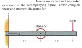
Transcribed Image Text:beams are loaded and supported
as shown in the accompanying figure: Draw complete
shear and moment diagrams for
600 Ib
2500 ft-lb
3ft
3 ft
Expert Solution
Step 1
The free-body diagram of the given beam is as shown below -
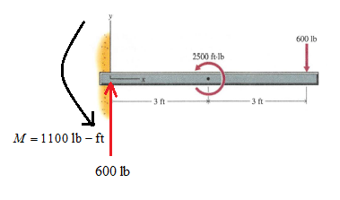
since there is only point load acting at the free end of the beam. Hence, the shear force diagram will rectangular.
The bending moment can be given as different can be,

Step by step
Solved in 2 steps with 2 images

Recommended textbooks for you
Mechanics of Materials (MindTap Course List)
Mechanical Engineering
ISBN:
9781337093347
Author:
Barry J. Goodno, James M. Gere
Publisher:
Cengage Learning
Mechanics of Materials (MindTap Course List)
Mechanical Engineering
ISBN:
9781337093347
Author:
Barry J. Goodno, James M. Gere
Publisher:
Cengage Learning