below, the capacitor has been charged to 10 V before the SW1 Vc(0-) = 10V switch is closed at t = 0. a) Find the differential equation for the current in the circuit, i(t), and express it in the standard form. b) Find es in terms of the circuit elements, R, L, C. c) Find in terms of R, L, C. d) If C = 1 µF and L= 10 mH, what value of R will make the system over damped? e) If the system is under damped, what is the general expression for the current in the resistor, VR (t). Do not solve for the constants. = C1 www R1
below, the capacitor has been charged to 10 V before the SW1 Vc(0-) = 10V switch is closed at t = 0. a) Find the differential equation for the current in the circuit, i(t), and express it in the standard form. b) Find es in terms of the circuit elements, R, L, C. c) Find in terms of R, L, C. d) If C = 1 µF and L= 10 mH, what value of R will make the system over damped? e) If the system is under damped, what is the general expression for the current in the resistor, VR (t). Do not solve for the constants. = C1 www R1

Introductory Circuit Analysis (13th Edition)
13th Edition
ISBN:9780133923605
Author:Robert L. Boylestad
Publisher:Robert L. Boylestad
Chapter1: Introduction
Section: Chapter Questions
Problem 1P: Visit your local library (at school or home) and describe the extent to which it provides literature...

Related questions

Question
number 2
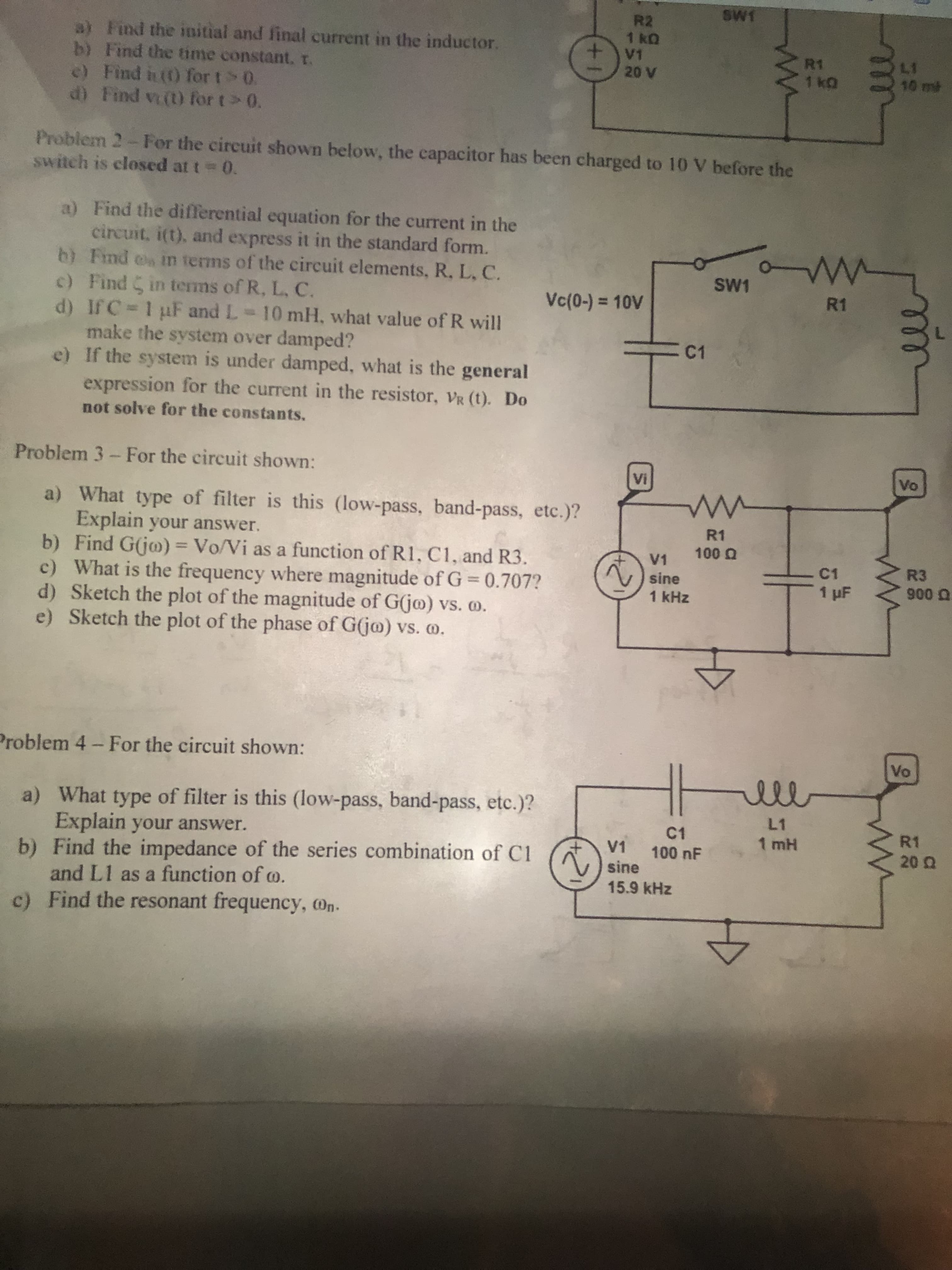
Transcribed Image Text:a) Find the initial and final current in the inductor.
R2
1kQ
V1
20 V
b) Find the time constant. T.
e) Find it (t) for t > 0.
d) Find vi(t) for t > 0.
switch is closed at t = 0.
Problem 2 - For the circuit shown below, the capacitor has been charged to 10 V before the
a)
Find the differential equation for the current in the
circuit, i(t), and express it in the standard form.
Find en in terms of the circuit elements, R, L, C.
c) Find in terms of R, L, C.
b)
SW1
Vc(0-) = 10V
d) If C = 1 µF and L= 10 mH, what value of R will
make the system over damped?
e)
If the system is under damped, what is the general
expression for the current in the resistor, VR (t). Do
not solve for the constants.
Problem 3 - For the circuit shown:
a) What type of filter is this (low-pass, band-pass, etc.)?
Explain your answer.
b) Find G(jo) = Vo/Vi as a function of R1, C1, and R3.
c) What is the frequency where magnitude of G=0.707?
d) Sketch the plot of the magnitude of G(jo) vs. 0.
e) Sketch the plot of the phase of G(jo) vs. o.
Problem 4 - For the circuit shown:
a)
What type of filter is this (low-pass, band-pass, etc.)?
Explain your answer.
b)
Find the impedance of the series combination of Cl
and L1 as a function of co.
c) Find the resonant frequency, On.
+1
Vi
SW1
C1
www
R1
100 Q
V1
sine
1 kHz
C1
V1 100 nF
sine
15.9 kHz
www
L1
1 mH
5
R1
1 KQ
W
R1
C1
1 µF
10 ml
Vo
ww
R3
900
Vo
R1
20 Q2
Expert Solution
This question has been solved!
Explore an expertly crafted, step-by-step solution for a thorough understanding of key concepts.

Step by step
Solved in 3 steps with 2 images

Knowledge Booster


Learn more about
Need a deep-dive on the concept behind this application? Look no further. Learn more about this topic, electrical-engineering and related others by exploring similar questions and additional content below.Recommended textbooks for you
Introductory Circuit Analysis (13th Edition)
Electrical Engineering
ISBN:
9780133923605
Author:
Robert L. Boylestad
Publisher:
PEARSON

Delmar's Standard Textbook Of Electricity
Electrical Engineering
ISBN:
9781337900348
Author:
Stephen L. Herman
Publisher:
Cengage Learning

Programmable Logic Controllers
Electrical Engineering
ISBN:
9780073373843
Author:
Frank D. Petruzella
Publisher:
McGraw-Hill Education
Introductory Circuit Analysis (13th Edition)
Electrical Engineering
ISBN:
9780133923605
Author:
Robert L. Boylestad
Publisher:
PEARSON
Delmar's Standard Textbook Of Electricity
Electrical Engineering
ISBN:
9781337900348
Author:
Stephen L. Herman
Publisher:
Cengage Learning
Programmable Logic Controllers
Electrical Engineering
ISBN:
9780073373843
Author:
Frank D. Petruzella
Publisher:
McGraw-Hill Education

Fundamentals of Electric Circuits
Electrical Engineering
ISBN:
9780078028229
Author:
Charles K Alexander, Matthew Sadiku
Publisher:
McGraw-Hill Education

Electric Circuits. (11th Edition)
Electrical Engineering
ISBN:
9780134746968
Author:
James W. Nilsson, Susan Riedel
Publisher:
PEARSON

Engineering Electromagnetics
Electrical Engineering
ISBN:
9780078028151
Author:
Hayt, William H. (william Hart), Jr, BUCK, John A.
Publisher:
Mcgraw-hill Education,