Bscale shown in the figure below in it

Delmar's Standard Textbook Of Electricity
7th Edition
ISBN:9781337900348
Author:Stephen L. Herman
Publisher:Stephen L. Herman
Chapter19: Capacitors
Section: Chapter Questions
Problem 2PA: You are an electrician working in an industrial plant. You discover that the problem with a certain...

Related questions
Question
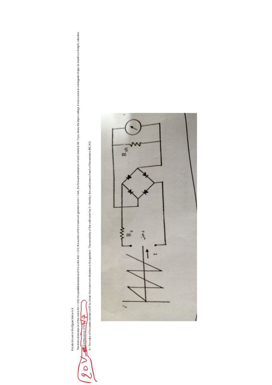
Transcribed Image Text:B scale shown in the figure below in it
The internal resistance of the coil is Rm = 200, the parallel resistance of the col is Rsh=200, the current of the maximum gradient is Im=1mA, the forward resistance of each diode is 50. If you know the input voltage, it was a wave in a triangular shape, its maximum height, calculate
at a frequency of 507
A-The value of the series resistance RS to obtain the maximum deviation in the gradient-The sensitivity of the voltmeter Sac 3-Mention the usefulness of each of the resistors (RS, RS)
WW=
www
R₁
Rsh
19
Expert Solution
This question has been solved!
Explore an expertly crafted, step-by-step solution for a thorough understanding of key concepts.

Step by step
Solved in 2 steps with 2 images

Knowledge Booster


Learn more about
Need a deep-dive on the concept behind this application? Look no further. Learn more about this topic, electrical-engineering and related others by exploring similar questions and additional content below.Recommended textbooks for you
Delmar's Standard Textbook Of Electricity
Electrical Engineering
ISBN:
9781337900348
Author:
Stephen L. Herman
Publisher:
Cengage Learning

Electricity for Refrigeration, Heating, and Air C…
Mechanical Engineering
ISBN:
9781337399128
Author:
Russell E. Smith
Publisher:
Cengage Learning
Delmar's Standard Textbook Of Electricity
Electrical Engineering
ISBN:
9781337900348
Author:
Stephen L. Herman
Publisher:
Cengage Learning
Electricity for Refrigeration, Heating, and Air C…
Mechanical Engineering
ISBN:
9781337399128
Author:
Russell E. Smith
Publisher:
Cengage Learning