Choose any 3 examples of Graph models from Examples 3-14 of Section 10.1 and explain for each what it means for them to be/to have a) directed/undirected, b) multiple edges allowed between same endpoints, and c) loops allowed answer 7 8 9
Choose any 3 examples of Graph models from Examples 3-14 of Section 10.1 and explain for each what it means for them to be/to have a) directed/undirected, b) multiple edges allowed between same endpoints, and c) loops allowed answer 7 8 9

Database System Concepts
7th Edition
ISBN:9780078022159
Author:Abraham Silberschatz Professor, Henry F. Korth, S. Sudarshan
Publisher:Abraham Silberschatz Professor, Henry F. Korth, S. Sudarshan
Chapter1: Introduction
Section: Chapter Questions
Problem 1PE

Related questions
Question
Choose any 3 examples of Graph models from Examples 3-14 of Section 10.1 and explain for each what it means for them to be/to have
a) directed/undirected,
b) multiple edges allowed between same endpoints, and
c) loops allowed
answer 7 8 9
Transcribed Image Text:List of the Experiments.pdf
PDF
1552369063907-05 AMO -Emero X
PDE Medical-Certificate-for-Student-
POF maddie_receipt.pdf
PDE Discrete_Mathematics_and_Its_A X
+
File | C:/Users/neera/Downloads/Compressed/all%20compiled/Third%20Sem/Maths/Discrete_Mathematics_and_lts_Appl.. Q
9 New Tab
f Facebook
Netflix
2 Мaps
GE News
Apple
iCloud
YouTube
A Internet Speed Test..
= Contents
of 1071
Q
(D Page view
A Read aloud
T Add text
Draw
E Highlight
Erase
668
first document cites the second in its eitation list. (In an academic paper, the citation list is the
bibliography, or list of references; in a patent it is the list of previous patents that are cited: and
in a legal opinion it is the list of previous opinions cited.) A citation graph is a directed graph
without loops or multiple edges.
SOFTWARE DESIGN APPLICATIONS Graph models are useful tools in the design of
software. We will briefly describe two of these models here.
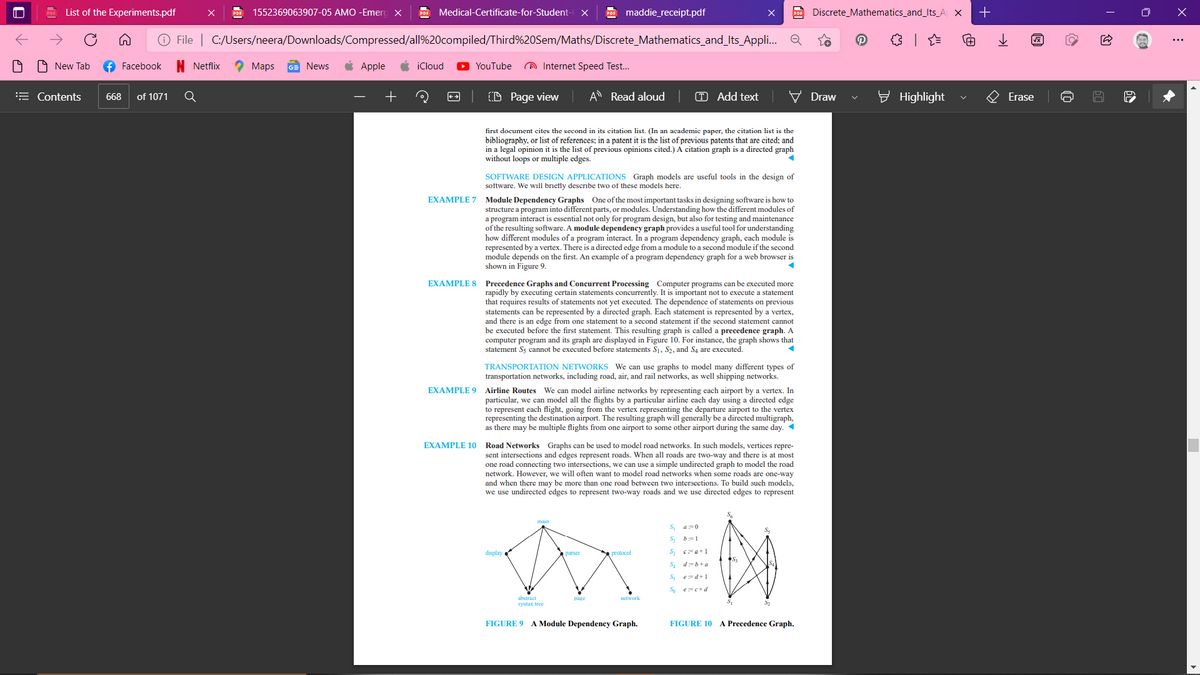
EXAMPLE 7 Module Dependency Graphs One of the most important tasks in designing software is how to
structure a program into different parts, or modules. Understanding how the different modules of
a program interact is essential not only for program design, but also for testing and maintenance
of the resulting software. A module dependency graph provides a useful tool for understanding
how different modules of a program interact. In a program dependency graph, each module is
represented by a vertex. There is a directed edge from a module to a second module if the second
module depends on the first. An example of a program dependency graph for a web browser is
shown in Figure 9.
EXAMPLE 8
Precedence Graphs and Concurrent Processing Computer programs can be executed more
rapidly by executing certain statements concurrently. It is important not to execute a statement
that requires results of statements not yet executed. The dependence of statements on previous
statements can be represented by a directed graph. Each statement is represented by a vertex,
and there is an edge from one statement to a second statement if the second statement cannot
be executed before the first statement. This resulting graph is called a precedence graph. A
computer program and its graph are displayed in Figure 10. For instance, the graph shows that
statement S5 cannot be executed before statements S1, S2, and S4 are executed.
TRANSPORTATION NETWORKS We can use graphs to model many different types of
transportation networks, including road, air, and rail networks, as well shipping networks.
EXAMPLE 9 Airline Routes We can model airline networks by representing each airport by a vertex. In
particular, we can model all the flights by a particular airline each day using a directed edge
to represent each flight, going from the vertex representing the departure airport to the vertex
representing the destination airport. The resulting graph will generally be a directed multigraph,
as there may be multiple flights from one airport to some other airport during the same day. 1
EXAMPLE 10 Road Networks Graphs can be used to model road networks. In such models, vertices repre-
sent intersections and edges represent roads. When all roads are two-way and there is at most
one road connecting two intersections, we can use a simple undirected graph to model the road
network. However, we will often want to model road networks when some roads are one-way
and when there may be more than one road between two interscctions. To build such models,
we use undirected edges to represent two-way roads and we use directed edges to represent
S
a:=0
b:=1
display
protocol
parser
S. d=b+a
e:=d+1
S6 e=e+d
abstract
syntax tree
page
network
32
FIGURE 9 A Module Dependency Graph.
FIGURE 10
A Precedence Graph.
Expert Solution
This question has been solved!
Explore an expertly crafted, step-by-step solution for a thorough understanding of key concepts.

Step by step
Solved in 2 steps with 3 images

Knowledge Booster


Learn more about
Need a deep-dive on the concept behind this application? Look no further. Learn more about this topic, computer-science and related others by exploring similar questions and additional content below.Recommended textbooks for you
Database System Concepts
Computer Science
ISBN:
9780078022159
Author:
Abraham Silberschatz Professor, Henry F. Korth, S. Sudarshan
Publisher:
McGraw-Hill Education

Starting Out with Python (4th Edition)
Computer Science
ISBN:
9780134444321
Author:
Tony Gaddis
Publisher:
PEARSON

Digital Fundamentals (11th Edition)
Computer Science
ISBN:
9780132737968
Author:
Thomas L. Floyd
Publisher:
PEARSON
Database System Concepts
Computer Science
ISBN:
9780078022159
Author:
Abraham Silberschatz Professor, Henry F. Korth, S. Sudarshan
Publisher:
McGraw-Hill Education
Starting Out with Python (4th Edition)
Computer Science
ISBN:
9780134444321
Author:
Tony Gaddis
Publisher:
PEARSON
Digital Fundamentals (11th Edition)
Computer Science
ISBN:
9780132737968
Author:
Thomas L. Floyd
Publisher:
PEARSON

C How to Program (8th Edition)
Computer Science
ISBN:
9780133976892
Author:
Paul J. Deitel, Harvey Deitel
Publisher:
PEARSON

Database Systems: Design, Implementation, & Manag…
Computer Science
ISBN:
9781337627900
Author:
Carlos Coronel, Steven Morris
Publisher:
Cengage Learning

Programmable Logic Controllers
Computer Science
ISBN:
9780073373843
Author:
Frank D. Petruzella
Publisher:
McGraw-Hill Education