Cohhecting the inductor to current source, 2 2 and 8 n resistors. After a long time, at c nductor is then connected to the pair of 30n resistors on the right. For this system: (a) Draw "Circuit A" and "Circuit B" like in in-class problems. Le. draw the circuit bo flipped (b) Will the current i, be a natural response or step response for time t > 0? (c) Find the expression i,(t) that describes the current through the inductor for t >0


Sinusoids And Phasors
Sinusoids are defined as the mathematical waveforms that are used to describe the nature of periodic oscillations.
Circuit Theory
Electric circuits are a network that comprises of a closed-loop, which helps in providing a return path for the current through a switch. When the switch is activated, the load operates, and the current accepts a path to finish the circuit at a low potential level from the opposing high potential level. Electric circuits theory is a linear analysis that helps in establishing a linear relation of voltage and current for R (resistance), L (inductance), and C (capacitance).

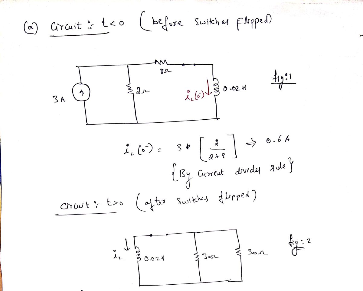
(b)
since, the inductor is allowed to dissipate the energy stored after t>0,the current iL is a natural response

Step by step
Solved in 3 steps with 2 images


