Common emitter amplifier. (a) 
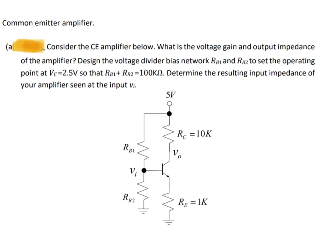
5. Consider the CE amplifier below. What is the voltage gain and output impedance of the amplifier? Design the voltage divider bias network RB1 and RB2 to set the operating point at Vc=2.5V so that RB1+ RB2 =100K. Determine the resulting input impedance of your amplifier seen at the input vi. 5V RBl Vi RB2 Rc =10K RE =1K
Q: What is the algebraic sum of the voltages and the currents around the loop in a circuit ?
A: In this question, we need to determine the algebraic sum of the voltages and the currents around the…
Q: I hope you can clarify how to draw a small triangle accurately.
A: Step 1:The transconductance (gm) of a JFET can be calculated using the following formula: gm = 2…
Q: 23 consider the finite-Length sequence b xen)= Sens+2cn-5). find the 10-Point discrete. - sequence…
A: Step 1:Step 2:
Q: Please do not rely too much on chatgpt, because its answer may be wrong. Please consider it…
A: From the given information we write the truth table as -truth table:-Now K-Map--010111110-01111
Q: Design a circuit that amplifies a 500 mV signal originating from a computer keyboard, so that this…
A: To amplify a 500 mV signal from a computer keyboard for interpretation by digital circuits on a…
Q: Write code matlab with comment Part b
A: As mentioned in the question, only we need to answer (b) part. Given:we need to plot above signal…
Q: QUESTION 1 What practical skills were taught and assessed in you Electronic Engineering lab? Choose…
A: A, B, D, and E are practical skills typically taught and assessed in an Electronic Engineering…
Q: 8. We have two push buttons A and B. Design a 3-digit BCD counter that: - counts from 000 to 999 if…
A: The objective of this question is to design a 3-digit BCD (Binary Coded Decimal) counter with…
Q: solve by using node voltage method and find Vo
A: Step 1: Step 2: Step 3: Step 4:
Q: Evaluate the circuit behavior for t<0 and t> 0 to determine the expression some incorrect I…
A:
Q: thank you
A: First, we need to calculate the cross-sectional area ((A)) of the core. Since the depth is given as…
Q: नत Series RL Circuit Find i(t) for to Given i(o) = 4A, V(0)=8V Redraw circuit in s-domain -34 352 m…
A: Step 1:Step 2:Step 3:Step 4:
Q: no ai, plz explain step by step
A: Step 1: Step 2:
Q: Calculate the wavelength of each band gap of solar cell materials. 2.5 eV лач 2ns n-Cds 10.9 eV CB…
A: a)To calculate the wavelength of light corresponding to a given energy, you can use the…
Q: Determine the rms values of each of the following (a) v(t) = 100 sin(ωt) V Vrms = 70.7V (b) i(t) = 8…
A:
Q: Convert the following decimal number to the binary format: 15 (in decimal) = (in binary) O 1011 O…
A:
Q: Calculate the time constant of the circuit shown. Enter your answer in units of microseconds us…
A: Step 1: Step 2: Step 3: Step 4:
Q: A 400V three-phase, four wire dystem has the following loads connected: Phase 1: Load impedance Z1=…
A:
Q: 4.2. The illumination levels in two different points, 0.75m away from each other, are 450 and 275…
A: Given:The illumination levels in two different points 0.75 m away from each other are 450 and 275…
Q: Ise the long method STEP BY STEP process: 3. Solve for I2 4. Solve for I3
A: Step 1: We begin by assigning node labels to the given circuit as shown in the figure below:Step 2:…
Q: By connecting 4 batteries in parallel of 12 volts, What voltage will the voltmeter in the figure…
A: The total voltage of the 4 batteries that are connected in parallel circuit is:…
Q: Draw the Output Waveforms: Analyze and draw the output waveforms for the following digital circuits,…
A: D Latch (Active-High Enable):Step 1: Enable Check (E High):If the Enable signal (E) is high, the…
Q: Fill the blank A) 2.000 sin (5t - 9°) at t= 0, 0.01, and 0.1 s. (Round the final answer to four…
A:
Q: We found the following specifications of an RTD temperature sensor from the datasheet: The…
A:
Q: None
A: Method 1: Pure circuit analysis Method 2: Conceptual analysis
Q: This is a practice question from the Signal and Systems course of my Electrical Engineering Program.…
A: And x(n) can be written using delta signal x(n) = δ(n)+δ(n + 1) - δ(n+2) If you…
Q: (b) i(t) (t = 50ms is period of waveform b.) here is my answer i(t) = 10sin(125.66t + 120o)A can you…
A:
Q: In the figure below, R₁ = 9.00R, the ammeter resistance is zero, and the battery is ideal. What…
A: Step 1:Step 2:
Q: Given the open-loop transfer function of the control system: G(s) = 800(s + 0.5) (s+9)(s² + 2s + 25)…
A: From the Bode plot, we can determine the following parameters:Gain margin: The gain margin is the…
Q: Please do not rely too much on chatgpt, because its answer may be wrong. Please consider it…
A: Step 1: Basics from my own notes: Step 2: From the given memory see that: • at the input port…
Q: For the 4-bit binary values in the table below, show the equivalent decimal values when the data is…
A: Please comment down for any doubt. I hope my answer helps you.
Q: Determine the impedance of an inductor that has the value provided at the given frequency at 100 mH…
A: To determine the impedance (Z) of an inductor at a given frequency, we can use the formula for…
Q: 7.1. The stator of a three-phase, 60-Hz, 8-pole synchronous generator has 48 slots. Determine (a)…
A: a) To determine the speed of the rotor of the synchronous generator, we can use the formula:…
Q: it already has the answer. I just need to some details and explanation
A:
Q: between total current and the current in the capacitor 1. The input voltage V; is sinusoidal.…
A:
Q: 6. Define and explain the following terms as applied to protective relaying: (i) Pick-up value (ii)…
A: In protective relaying, these terms are crucial in determining when and how the protective devices…
Q: Write, if the shown statements are true or false, (Hint: you will lose points for each incorrect…
A: Step 1: Step 2: Step 3: Step 4:
Q: Please answer in typing format
A: The function of each block and how this 3-bit binary ripple counter circuit works: JK Flip-Flops:The…
Q: 2. We found the following specifications of an RTD temperature sensor from the datasheet: The…
A: Step 1:To find the transfer function of the RTD (Resistance Temperature Detector), we can use the…
Q: *Construct a JK flip-flop using a D flip-flop, a two-to-one-line multiplexer, and an inverter.…
A: Step 1: Step 2: Step 3: Step 4:
Q: Write the Binary-coded decimal (BCD) code of the following decimal number: 105.4 (in decimal) = (in…
A:
Q: Please answer in typing format
A: Step 1: as seen from circuit first we will finding out the voltage at point A as seen in the…
Q: Q6. (A Criteria 3.2,3.6) A circuit is required to convert a DC supply voltage of 12 Volts to 5 volts…
A: The objective of the question is to design a voltage regulator circuit using a Zener diode that…
Q: If the equivalent resistance is 4K ohm as seen by the source, show the steps to find this and the…
A:
Q: Create Truth table and logic diagram using basic gates F = X +YZ
A: The objective of the question is to create a truth table and logic diagram for the given Boolean…
Q: Explore the rates of adoption of the most widely used renewable energy resources
A: Renewable energy resources have garnered increasing interest in recent years due to their ability to…
Q: A customer has sent in a transformer for repair, with the following information on its nameplate: Dz…
A: Grouping transformers is necessary for several reasons:Voltage Compatibility: Transformers are often…
Q: please help i will like.
A: Step 1 : First, let's align the numbers vertically, just like you would with decimal numbers: 1…
Q: 8. Clock, and S, R waveforms are shown below for a positive edge-triggered SR flip flop. Sketch the…
A: Step 1: Step 2: Step 3: Step 4:
Q: Solve step by step and asap
A:
Trending now
This is a popular solution!
Step by step
Solved in 2 steps with 2 images
- In the common-emitter amplifier circuit shown in the figure, Vcc=9V, R1=27kΩ, R2=15kΩ, RE=1.2kΩ and RC=2.2kΩ. The transistor has β=100.a-) If Rsig=10kΩ and RL=2kΩ, calculate the IE value of the amplifier.b-) For small signal analysis of the transistor, find the value of Rin by deriving the π-modelc-) Calculate vo/vsig and io/ii.The dc bias circuit for a common emitter amplifier is shown in the figure. In the circuit, Vcc=15v,RB1=20k Ω,RB2=100k Ω,Rc=5.1k Ω,and RE1=1k Ω, Assume that when the transistor is on, the voltage drop from base to emitter VBE=0.7v. Also assume that β= ∞, which implies that the base current can be considered zero (IB=0) in your calculations. Solve for the base voltage VB. Solve for the emitter voltage VE. Solve for the emitter current IB. Solve for the collector current ICthe transistor in the circuit above has gm=0.11mS and ro=33Kohm. Given the following condition: R1=770Kohm, R2=890Kohm, RD=5.4Kohm, R3=20Kohm, R6=6.9Kohm, Rsig=2Kohm, determine the input impedance of the amplifier in Kohm.
- For the amplifier as shown, VDD = 12 V, VSS = 12 V, ISS = 20 μA, and RD = 820 kΩ. Assume IDSS = 1 mA and VP = +2 V. (a) What are the output voltages υo for the amplifier for υ1 = 0V and υ1 = 20 mV? (b) What is the maximum permissible value of υs?Design a Single-Stage Common Emitter Class A Amplifier Specifications:Voltage Divider Bias Circuit Supply: Any value from 10Vdc to 24VdcLoad: 1kΩVoltage Gain: Any value from 80 to 400Lower Cutoff Frequency: 100 HzSinusoidal source (zero internal resistance): 50mVp-pTransistor: Si, β = 75 • Base-Collector capacitance = 8pF • Base-Emitter Capacitance = 25pF a) compute for the biasing resistances.b) determine the dc transistor terminal voltages and transistor currents.a) Differentiate between Common Emitter (CE), Common Collector (CC) and Common Base (CB) amplifiers. b) Do the DC Analysis of the circuit below and find out the DC collector voltage?c) Do the AC Analysis of the circuit below and find out the AC collector voltage?R1=30kΩΩ=610Ω
- For the given amplifier circuit, asnwer the following question: a) For R1= 12 kΩ, R2= 10 kΩ, RE= 1 kΩ, RC = 1.2 kΩ, determine the following dc parameters: VB, VE, IE, and VC . (assume stiff voltage divider) b) For r’e = 5.5 Ω, R1= 12 kΩ, R2= 10 kΩ, RE= 1 kΩ, RC = 1.2 kΩ, RL = 7.5 kΩ, RS = 500 Ω, determine the input resistance at the base ( Rin(base) ), the total input resistance ( Rin(tot) ), voltage gain (Av) ,and attenaution. c) Assume that the overall voltage gain A’v = 120, the dc collector voltage VC = 6.3 V, and Vin = 15 mV rms. Determine the ac collector voltage (Vc) , then draw the total collector voltage waveform d) For r’e = 5.5 Ω, RE= 1 kΩ, RC = 1.2 kΩ, RL = 7.5 kΩ, determine the voltage gain if C2 is removed. Explain the effect of removing C2 on gain stability.SOLVE NUMBER 2 .1. Solve the output voltage if the gain is 24 db with aninput of 5mV.? 2. Assume a load resistor, RL of 2.2kΩs and a supply voltage of 24v. Calculate the Collector current (Ic) flowing through the load resistor when the transistor is switched fully "ON", assume Vce = 0, & β = 100. Also find the value of the Emitter resistor, Re with a voltage drop of 1.3v across it, R1, R2, and Ib. Assume also a value of 9 times Ib flowing through the resistor R2, while 10 times Ib flowing through R1.What is the voltage gain of the common-emitter amplifier as shown? Assume βF = 135, VCC = VEE = 10 V, R1 = 20 kΩ, R2 = 62 kΩ,RC = 13 kΩ, and RE = 3.9 kΩ.
- In the circuit given in the figure, what is the voltage gain (Av) of the circuit when = 100, r0 = 40 kΩ, RB = 360 kΩ, RC = 3.3 kΩ, RE = 220 Ω, Rs = 15 kΩ and RL = 166 kΩ?NOTE-1: The output impedance r0 of the transistor will be taken into the calculations.NOTE-2: Capacitors are negligible at mid-band frequency.Since the transistors used in the circuit are B=100, ro=∞ a) Find the re1, re2 resistance values by performing the DC analysis for each amplifier stage separately. b) Draw the AC equivalent circuit of the amplifier circuit. c)Find the input and output impedance values for each amplifier stage. d) Find the voltage gains AV1, AV2 for each amplifier stage. e) Find the voltage value VL by finding the AV1 Voltage gain.A common emitter amplifier as shown in Figure Q2 has the following parameters, β = 100, R1= 33K, R2 = 10K, RC = 3K3, RE = 1K, ro = and VBE = 0.7 V.State all assumptions made.i. Check whether βRE>>10R2 is satisfiedii. Use the appropriate approach of analysis to determine the Quiescent point; IBQ,ICQ and VCEQ.iii. Draw the small signal equivalent circuit. Determine input impedance, Zin, outputimpedance, Zout, and the voltage gain, AV, if RL=20kΩ.