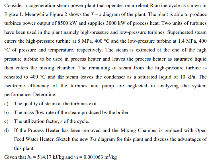
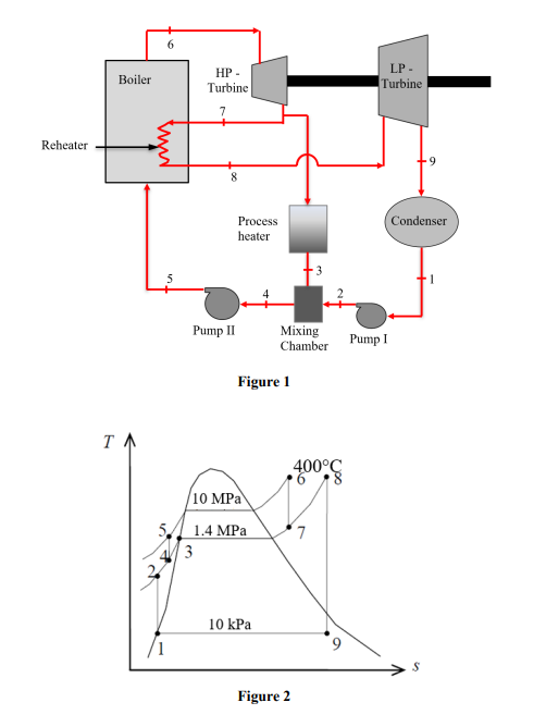
Consider a cogeneration steam power plant that operates on a reheat Rankine cycle as shown in Figure 1. Meanwhile Figure 2 shows the T – s diagram of the plant. The plant is able to produce turbines power output of 8500 kW and supplies 3000 kW of process heat. Two units of turbines have been used in the plant namely high-pressure and low-pressure turbines. Superheated steam enters the high-pressure turbine at 8 MPa, 400 °C and the low-pressure turbine at 1.4 MPa, 400 °C of pressure and temperature, respectively. The steam is extracted at the end of the high pressure turbine to be used in process heater and leaves the process heater as saturated liquid then enters the mixing chamber. The remaining of steam from the high-pressure turbine is reheated to 400 °C and the steam leaves the condenser as a saturated liquid of 10 kPa. The isentropic efficiency of the turbines and pump are neglected in analyzing the system
Consider a cogeneration steam power plant that operates on a reheat Rankine cycle as shown in Figure 1. Meanwhile Figure 2 shows the T – s diagram of the plant. The plant is able to produce turbines power output of 8500 kW and supplies 3000 kW of process heat. Two units of turbines have been used in the plant namely high-pressure and low-pressure turbines. Superheated steam enters the high-pressure turbine at 8 MPa, 400 °C and the low-pressure turbine at 1.4 MPa, 400 °C of pressure and temperature, respectively. The steam is extracted at the end of the high pressure turbine to be used in process heater and leaves the process heater as saturated liquid then enters the mixing chamber. The remaining of steam from the high-pressure turbine is reheated to 400 °C and the steam leaves the condenser as a saturated liquid of 10 kPa. The isentropic efficiency of the turbines and pump are neglected in analyzing the system

Elements Of Electromagnetics
7th Edition
ISBN:9780190698614
Author:Sadiku, Matthew N. O.
Publisher:Sadiku, Matthew N. O.
ChapterMA: Math Assessment
Section: Chapter Questions
Problem 1.1MA

Related questions
Question
Transcribed Image Text:Consider a cogeneration steam power plant that operates on a reheat Rankine cycle as shown in
Figure 1. Meanwhile Figure 2 shows the T – s diagram of the plant. The plant is able to produce
turbines power output of 8500 kW and supplies 3000 kW of process heat. Two units of turbines
have been used in the plant namely high-pressure and low-pressure turbines. Superheated steam
enters the high-pressure turbine at 8 MPa, 400 °C and the low-pressure turbine at 1.4 MPa, 400
°C of pressure and temperature, respectively. The steam is extracted at the end of the high
pressure turbine to be used in process heater and leaves the process heater as saturated liquid
then enters the mixing chamber. The remaining of steam from the high-pressure turbine is
reheated to 400 °C and the steam leaves the condenser as a saturated liquid of 10 kPa. The
isentropic efficiency of the turbines and pump are neglected in analyzing the system
performance. Determine:
a) The quality of steam at the turbines exit.
b) The mass flow rate of the steam produced by the boiler.
c) The utilization factor, ɛ of the cycle.
d) If the Process Heater has been removed and the Mixing Chamber is replaced with Open
Feed Water Heater. Sketch the new T-s diagram for this plant and discuss the advantages of
this plant.
Given that h4 = 514.17 kJ/kg and v4 = 0.001063 m²/kg
Transcribed Image Text:HP -
LP -
Boiler
Turbine
Turbine
7
Reheater
Condenser
Process
heater
Pump II
Мixing
Pump I
Chamber
Figure 1
400°C
/10 MPa
5 1.4 MPa
1 3
7
10 kPa
Figure 2
Expert Solution
This question has been solved!
Explore an expertly crafted, step-by-step solution for a thorough understanding of key concepts.

This is a popular solution!

Trending now
This is a popular solution!

Step by step
Solved in 2 steps with 2 images

Knowledge Booster


Learn more about
Need a deep-dive on the concept behind this application? Look no further. Learn more about this topic, mechanical-engineering and related others by exploring similar questions and additional content below.Recommended textbooks for you
Elements Of Electromagnetics
Mechanical Engineering
ISBN:
9780190698614
Author:
Sadiku, Matthew N. O.
Publisher:
Oxford University Press

Mechanics of Materials (10th Edition)
Mechanical Engineering
ISBN:
9780134319650
Author:
Russell C. Hibbeler
Publisher:
PEARSON

Thermodynamics: An Engineering Approach
Mechanical Engineering
ISBN:
9781259822674
Author:
Yunus A. Cengel Dr., Michael A. Boles
Publisher:
McGraw-Hill Education
Elements Of Electromagnetics
Mechanical Engineering
ISBN:
9780190698614
Author:
Sadiku, Matthew N. O.
Publisher:
Oxford University Press
Mechanics of Materials (10th Edition)
Mechanical Engineering
ISBN:
9780134319650
Author:
Russell C. Hibbeler
Publisher:
PEARSON
Thermodynamics: An Engineering Approach
Mechanical Engineering
ISBN:
9781259822674
Author:
Yunus A. Cengel Dr., Michael A. Boles
Publisher:
McGraw-Hill Education

Control Systems Engineering
Mechanical Engineering
ISBN:
9781118170519
Author:
Norman S. Nise
Publisher:
WILEY

Mechanics of Materials (MindTap Course List)
Mechanical Engineering
ISBN:
9781337093347
Author:
Barry J. Goodno, James M. Gere
Publisher:
Cengage Learning

Engineering Mechanics: Statics
Mechanical Engineering
ISBN:
9781118807330
Author:
James L. Meriam, L. G. Kraige, J. N. Bolton
Publisher:
WILEY