Consider a two-stage cascade refrigeration system operating between the pressure limits of 1.2 MPa and 200kPa with refrigerant-134a as the working fluid (s. figure B). The refrigerant leaves the condenser as a saturated liquid and is throttled to a flash chamber operating at 0.4 MPa. In the flash chamber, the refrigerant is separated into saturated vapor (point 3) and saturated liquid (point 7). The vapor (point 3) is mixed with the refrigerant leaving the low pressure compressor. The mixture (point 9) is then compressed to the condenser pressure by the high-pressure compressor. The saturated liquid in the flash chamber is throttled to the evaporator pressure and cools the refrigerated space as it vaporizes in the evaporator. The mass flow rate of the refrigerant through the low-pressure compressor is 0.15 kg/s. Assuming the refrigerant leaves the evaporator as a saturated vapor and the isentropic coefficient is 80% for both adiabatic compressors, determine : (a) each point of the refrigeration cycle and show the entire process in a T-s diagram (b) the temperatures of the working fluid at points 2,9, and 4 (c) the mass flow rate of the refrigerant through the high-pressure compressor (d) the rate of heat removal from the refrigerated space in kW (e) the coefficient of performance (COP) of this refrigerator (f) the rate of heat removal and the COP, if this refrigerator operated on a single-stage cycle between the same pressure limits with the same compressor efficiency and the same flow rate as in part (a).
Consider a two-stage cascade refrigeration system operating between the pressure limits of 1.2 MPa and 200kPa with refrigerant-134a as the working fluid (s. figure B). The refrigerant leaves the condenser as a saturated liquid and is throttled to a flash chamber operating at 0.4 MPa. In the flash chamber, the refrigerant is separated into saturated vapor (point 3) and saturated liquid (point 7). The vapor (point 3) is mixed with the refrigerant leaving the low pressure compressor. The mixture (point 9) is then compressed to the condenser pressure by the high-pressure compressor. The saturated liquid in the flash chamber is throttled to the evaporator pressure and cools the refrigerated space as it vaporizes in the evaporator. The mass flow rate of the refrigerant through the low-pressure compressor is 0.15 kg/s. Assuming the refrigerant leaves the evaporator as a saturated vapor and the isentropic coefficient is 80% for both adiabatic compressors, determine : (a) each point of the refrigeration cycle and show the entire process in a T-s diagram (b) the temperatures of the working fluid at points 2,9, and 4 (c) the mass flow rate of the refrigerant through the high-pressure compressor (d) the rate of heat removal from the refrigerated space in kW (e) the coefficient of performance (COP) of this refrigerator (f) the rate of heat removal and the COP, if this refrigerator operated on a single-stage cycle between the same pressure limits with the same compressor efficiency and the same flow rate as in part (a).

Refrigeration and Air Conditioning Technology (MindTap Course List)
8th Edition
ISBN:9781305578296
Author:John Tomczyk, Eugene Silberstein, Bill Whitman, Bill Johnson
Publisher:John Tomczyk, Eugene Silberstein, Bill Whitman, Bill Johnson
Chapter22: Condensers
Section: Chapter Questions
Problem 7RQ: When a standard-efficiency air-cooled condenser is used, the condensing refrigerant will normally be...

Related questions
Question
please solve AB
Transcribed Image Text:Consider a two-stage cascade refrigeration system operating between the
pressure limits of 1.2 MPa and 200kPa with refrigerant-134a as the working
fluid (s. figure B). The refrigerant leaves the condenser as a saturated liquid
and is throttled to a flash chamber operating at 0.4 MPa. In the flash chamber,
the refrigerant is separated into saturated vapor (point 3) and saturated
liquid (point 7). The vapor (point 3) is mixed with the refrigerant leaving the
low pressure compressor. The mixture (point 9) is then compressed to the
condenser pressure by the high-pressure compressor. The saturated liquid in
the flash chamber is throttled to the evaporator pressure and cools the
refrigerated space as it vaporizes in the evaporator. The mass flow rate of the
refrigerant through the low-pressure compressor is 0.15 kg/s. Assuming the
refrigerant leaves the evaporator as a saturated vapor and the isentropic
coefficient is 80% for both adiabatic compressors, determine :
(a) each point of the refrigeration cycle and show the entire process in a T-s
diagram
(b) the temperatures of the working fluid at points 2, 9, and 4
(c) the mass flow rate of the refrigerant through the high-pressure
compressor
(d) the rate of heat removal from the refrigerated space in kW
(e) the coefficient of performance (COP) of this refrigerator
(f) the rate of heat removal and the COP, if this refrigerator operated on a
single-stage cycle between the same pressure limits with the same
compressor efficiency and the same flow rate as in part (a).
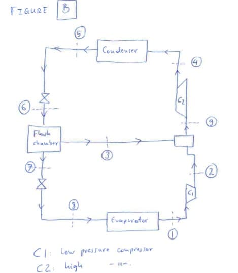
Transcribed Image Text:FIGURE
(5
Coudeuser
Flesh
chamber
(3
(8)
Evapovator
CI: Low pressare Compressor
C2: high
Expert Solution
This question has been solved!
Explore an expertly crafted, step-by-step solution for a thorough understanding of key concepts.

Step by step
Solved in 3 steps with 7 images

Knowledge Booster


Learn more about
Need a deep-dive on the concept behind this application? Look no further. Learn more about this topic, mechanical-engineering and related others by exploring similar questions and additional content below.Recommended textbooks for you
Refrigeration and Air Conditioning Technology (Mi…
Mechanical Engineering
ISBN:
9781305578296
Author:
John Tomczyk, Eugene Silberstein, Bill Whitman, Bill Johnson
Publisher:
Cengage Learning
Refrigeration and Air Conditioning Technology (Mi…
Mechanical Engineering
ISBN:
9781305578296
Author:
John Tomczyk, Eugene Silberstein, Bill Whitman, Bill Johnson
Publisher:
Cengage Learning