Example 1.3 Figure 1.17 depicts an amplifier composed of a cascade of three stages. The amplifier is fed by a signal source with a source resistance of 100 ks and delivers its output into a load resistance of 100 2. The first stage has a relatively high input resistance and a modest gain factor of 10. The second stage has a higher gain factor but lower input resistance. Finally, the last, or output, stage has unity gain but a low output resistance. We wish to evaluate the overall voltage gain, that is, v₁/v¸, the current gain, and the power gain. V₂ Example 1.3 continued Stage 1 Source | 100 ΚΩ i M + >1 ΜΩ 10% 1 kn M Figure 1.17 Three-stage amplifier for Example 1.3. or 58.3 dB. or 57.4 dB. + V12 100 kn 100 ₁2 or 138.3 dB. The power gain is found from or 98.3 dB. Note that V₁2 A₁ = = 10 Vil Solution The fraction of source signal appearing at the input terminals of the amplifier is obtained using the voltage-divider rule at the input, as follows: 1 ΜΩ 1 ΜΩ + 100 ΚΩ Stage 2 V ₁3 A2 = = 100- V₁2 10 ΚΩ 10 kΩ + 1 kΩ Finally, the voltage gain of the output stage is as follows: The current gain is found as follows: Vil Us The voltage gain of the first stage is obtained by considering the input resistance of the second stage to be the load of the first stage; that is, A₁ = A₁ = UL A3 = = 1 V ₁3 The total gain of the three stages in cascade can now be found from =A1A2A3 = 818 V/V VL Vil 1 kn 100 ΚΩ 100 kΩ + 1 kΩ Similarly, the voltage gain of the second stage is obtained by considering the input resistance of the third stage to be the load of the second stage, = 0.909 V/V 100 £2 100 Ω + 10 Ω UL VL Vil Vs Vil Us = 9.9 V/V =A₂ A, (dB) = • 10 ΚΩ = 90.9 V/V To find the voltage gain from source to load, we multiply A, by the factor representing the loss of gain at the input; that is, Vil V₂ = 818 x 0.909 = 743.6 V/V Stage 3 = 0.909 V/V v./100 Ω U/1 ΜΩ = 10¹ x A₂ = 8.18 × 10° A/A 173 P₁ ULIO P₁ vai = A, A₁ = 818 x 8.18 × 10° = 66.9 × 10³ W/W = =[A, (dB)+A; (dB)] 10 Q2 M Load 100 Ω ΤΣ Consider the cascade amplifier in Exercise #12 (Example 1.3). Find the overall v₁/v, obtained when the 1st and 2nd stages are interchanged. Compare this value with the result in Exercise #12 and comment.
Example 1.3 Figure 1.17 depicts an amplifier composed of a cascade of three stages. The amplifier is fed by a signal source with a source resistance of 100 ks and delivers its output into a load resistance of 100 2. The first stage has a relatively high input resistance and a modest gain factor of 10. The second stage has a higher gain factor but lower input resistance. Finally, the last, or output, stage has unity gain but a low output resistance. We wish to evaluate the overall voltage gain, that is, v₁/v¸, the current gain, and the power gain. V₂ Example 1.3 continued Stage 1 Source | 100 ΚΩ i M + >1 ΜΩ 10% 1 kn M Figure 1.17 Three-stage amplifier for Example 1.3. or 58.3 dB. or 57.4 dB. + V12 100 kn 100 ₁2 or 138.3 dB. The power gain is found from or 98.3 dB. Note that V₁2 A₁ = = 10 Vil Solution The fraction of source signal appearing at the input terminals of the amplifier is obtained using the voltage-divider rule at the input, as follows: 1 ΜΩ 1 ΜΩ + 100 ΚΩ Stage 2 V ₁3 A2 = = 100- V₁2 10 ΚΩ 10 kΩ + 1 kΩ Finally, the voltage gain of the output stage is as follows: The current gain is found as follows: Vil Us The voltage gain of the first stage is obtained by considering the input resistance of the second stage to be the load of the first stage; that is, A₁ = A₁ = UL A3 = = 1 V ₁3 The total gain of the three stages in cascade can now be found from =A1A2A3 = 818 V/V VL Vil 1 kn 100 ΚΩ 100 kΩ + 1 kΩ Similarly, the voltage gain of the second stage is obtained by considering the input resistance of the third stage to be the load of the second stage, = 0.909 V/V 100 £2 100 Ω + 10 Ω UL VL Vil Vs Vil Us = 9.9 V/V =A₂ A, (dB) = • 10 ΚΩ = 90.9 V/V To find the voltage gain from source to load, we multiply A, by the factor representing the loss of gain at the input; that is, Vil V₂ = 818 x 0.909 = 743.6 V/V Stage 3 = 0.909 V/V v./100 Ω U/1 ΜΩ = 10¹ x A₂ = 8.18 × 10° A/A 173 P₁ ULIO P₁ vai = A, A₁ = 818 x 8.18 × 10° = 66.9 × 10³ W/W = =[A, (dB)+A; (dB)] 10 Q2 M Load 100 Ω ΤΣ Consider the cascade amplifier in Exercise #12 (Example 1.3). Find the overall v₁/v, obtained when the 1st and 2nd stages are interchanged. Compare this value with the result in Exercise #12 and comment.

Introductory Circuit Analysis (13th Edition)
13th Edition
ISBN:9780133923605
Author:Robert L. Boylestad
Publisher:Robert L. Boylestad
Chapter1: Introduction
Section: Chapter Questions
Problem 1P: Visit your local library (at school or home) and describe the extent to which it provides literature...

Related questions
Question
![Example 1.3
Figure 1.17 depicts an amplifier composed of a cascade of three stages. The amplifier is fed by a signal
source with a source resistance of 100 ks and delivers its output into a load resistance of 100 2. The
first stage has a relatively high input resistance and a modest gain factor of 10. The second stage has a
higher gain factor but lower input resistance. Finally, the last, or output, stage has unity gain but a low
output resistance. We wish to evaluate the overall voltage gain, that is, v₁/v¸, the current gain, and the
power gain.
V₂
Example 1.3 continued
Stage 1
Source |
100 ΚΩ
i M
+
>1 ΜΩ
10%
1 kn
M
Figure 1.17 Three-stage amplifier for Example 1.3.
or 58.3 dB.
or 57.4 dB.
+
V12
100 kn 100 ₁2
or 138.3 dB.
The power gain is found from
or 98.3 dB. Note that
V₁2
A₁ = = 10
Vil
Solution
The fraction of source signal appearing at the input terminals of the amplifier is obtained using the
voltage-divider rule at the input, as follows:
1 ΜΩ
1 ΜΩ + 100 ΚΩ
Stage 2
V ₁3
A2 = = 100-
V₁2
10 ΚΩ
10 kΩ + 1 kΩ
Finally, the voltage gain of the output stage is as follows:
The current gain is found as follows:
Vil
Us
The voltage gain of the first stage is obtained by considering the input resistance of the second stage to be
the load of the first stage; that is,
A₁ =
A₁ =
UL
A3 = = 1
V ₁3
The total gain of the three stages in cascade can now be found from
=A1A2A3 = 818 V/V
VL
Vil
1 kn
100 ΚΩ
100 kΩ + 1 kΩ
Similarly, the voltage gain of the second stage is obtained by considering the input resistance of the third
stage to be the load of the second stage,
= 0.909 V/V
100 £2
100 Ω + 10 Ω
UL VL Vil
Vs Vil Us
= 9.9 V/V
=A₂
A, (dB) =
• 10 ΚΩ
= 90.9 V/V
To find the voltage gain from source to load, we multiply A, by the factor representing the loss of gain at
the input; that is,
Vil
V₂
= 818 x 0.909 = 743.6 V/V
Stage 3
= 0.909 V/V
v./100 Ω
U/1 ΜΩ
= 10¹ x A₂ = 8.18 × 10° A/A
173
P₁
ULIO
P₁
vai
= A, A₁ = 818 x 8.18 × 10° = 66.9 × 10³ W/W
= =[A, (dB)+A; (dB)]
10 Q2
M
Load
100 Ω ΤΣ](/v2/_next/image?url=https%3A%2F%2Fcontent.bartleby.com%2Fqna-images%2Fquestion%2F4fb02365-efda-4f71-9185-5332218a7cc4%2F93fa3cba-38c1-46c5-a374-58b33738d8e8%2Fvc8ahh_processed.png&w=3840&q=75)
Transcribed Image Text:Example 1.3
Figure 1.17 depicts an amplifier composed of a cascade of three stages. The amplifier is fed by a signal
source with a source resistance of 100 ks and delivers its output into a load resistance of 100 2. The
first stage has a relatively high input resistance and a modest gain factor of 10. The second stage has a
higher gain factor but lower input resistance. Finally, the last, or output, stage has unity gain but a low
output resistance. We wish to evaluate the overall voltage gain, that is, v₁/v¸, the current gain, and the
power gain.
V₂
Example 1.3 continued
Stage 1
Source |
100 ΚΩ
i M
+
>1 ΜΩ
10%
1 kn
M
Figure 1.17 Three-stage amplifier for Example 1.3.
or 58.3 dB.
or 57.4 dB.
+
V12
100 kn 100 ₁2
or 138.3 dB.
The power gain is found from
or 98.3 dB. Note that
V₁2
A₁ = = 10
Vil
Solution
The fraction of source signal appearing at the input terminals of the amplifier is obtained using the
voltage-divider rule at the input, as follows:
1 ΜΩ
1 ΜΩ + 100 ΚΩ
Stage 2
V ₁3
A2 = = 100-
V₁2
10 ΚΩ
10 kΩ + 1 kΩ
Finally, the voltage gain of the output stage is as follows:
The current gain is found as follows:
Vil
Us
The voltage gain of the first stage is obtained by considering the input resistance of the second stage to be
the load of the first stage; that is,
A₁ =
A₁ =
UL
A3 = = 1
V ₁3
The total gain of the three stages in cascade can now be found from
=A1A2A3 = 818 V/V
VL
Vil
1 kn
100 ΚΩ
100 kΩ + 1 kΩ
Similarly, the voltage gain of the second stage is obtained by considering the input resistance of the third
stage to be the load of the second stage,
= 0.909 V/V
100 £2
100 Ω + 10 Ω
UL VL Vil
Vs Vil Us
= 9.9 V/V
=A₂
A, (dB) =
• 10 ΚΩ
= 90.9 V/V
To find the voltage gain from source to load, we multiply A, by the factor representing the loss of gain at
the input; that is,
Vil
V₂
= 818 x 0.909 = 743.6 V/V
Stage 3
= 0.909 V/V
v./100 Ω
U/1 ΜΩ
= 10¹ x A₂ = 8.18 × 10° A/A
173
P₁
ULIO
P₁
vai
= A, A₁ = 818 x 8.18 × 10° = 66.9 × 10³ W/W
= =[A, (dB)+A; (dB)]
10 Q2
M
Load
100 Ω ΤΣ
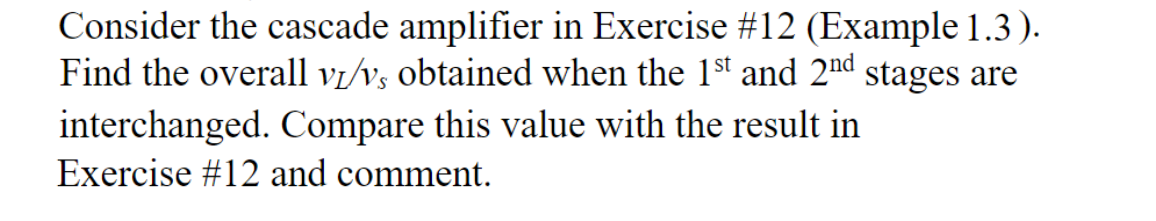
Transcribed Image Text:Consider the cascade amplifier in Exercise #12 (Example 1.3).
Find the overall v₁/v, obtained when the 1st and 2nd stages are
interchanged. Compare this value with the result in
Exercise #12 and comment.
AI-Generated Solution

Unlock instant AI solutions
Tap the button
to generate a solution
Recommended textbooks for you
Introductory Circuit Analysis (13th Edition)
Electrical Engineering
ISBN:
9780133923605
Author:
Robert L. Boylestad
Publisher:
PEARSON

Delmar's Standard Textbook Of Electricity
Electrical Engineering
ISBN:
9781337900348
Author:
Stephen L. Herman
Publisher:
Cengage Learning

Programmable Logic Controllers
Electrical Engineering
ISBN:
9780073373843
Author:
Frank D. Petruzella
Publisher:
McGraw-Hill Education
Introductory Circuit Analysis (13th Edition)
Electrical Engineering
ISBN:
9780133923605
Author:
Robert L. Boylestad
Publisher:
PEARSON
Delmar's Standard Textbook Of Electricity
Electrical Engineering
ISBN:
9781337900348
Author:
Stephen L. Herman
Publisher:
Cengage Learning
Programmable Logic Controllers
Electrical Engineering
ISBN:
9780073373843
Author:
Frank D. Petruzella
Publisher:
McGraw-Hill Education

Fundamentals of Electric Circuits
Electrical Engineering
ISBN:
9780078028229
Author:
Charles K Alexander, Matthew Sadiku
Publisher:
McGraw-Hill Education

Electric Circuits. (11th Edition)
Electrical Engineering
ISBN:
9780134746968
Author:
James W. Nilsson, Susan Riedel
Publisher:
PEARSON

Engineering Electromagnetics
Electrical Engineering
ISBN:
9780078028151
Author:
Hayt, William H. (william Hart), Jr, BUCK, John A.
Publisher:
Mcgraw-hill Education,