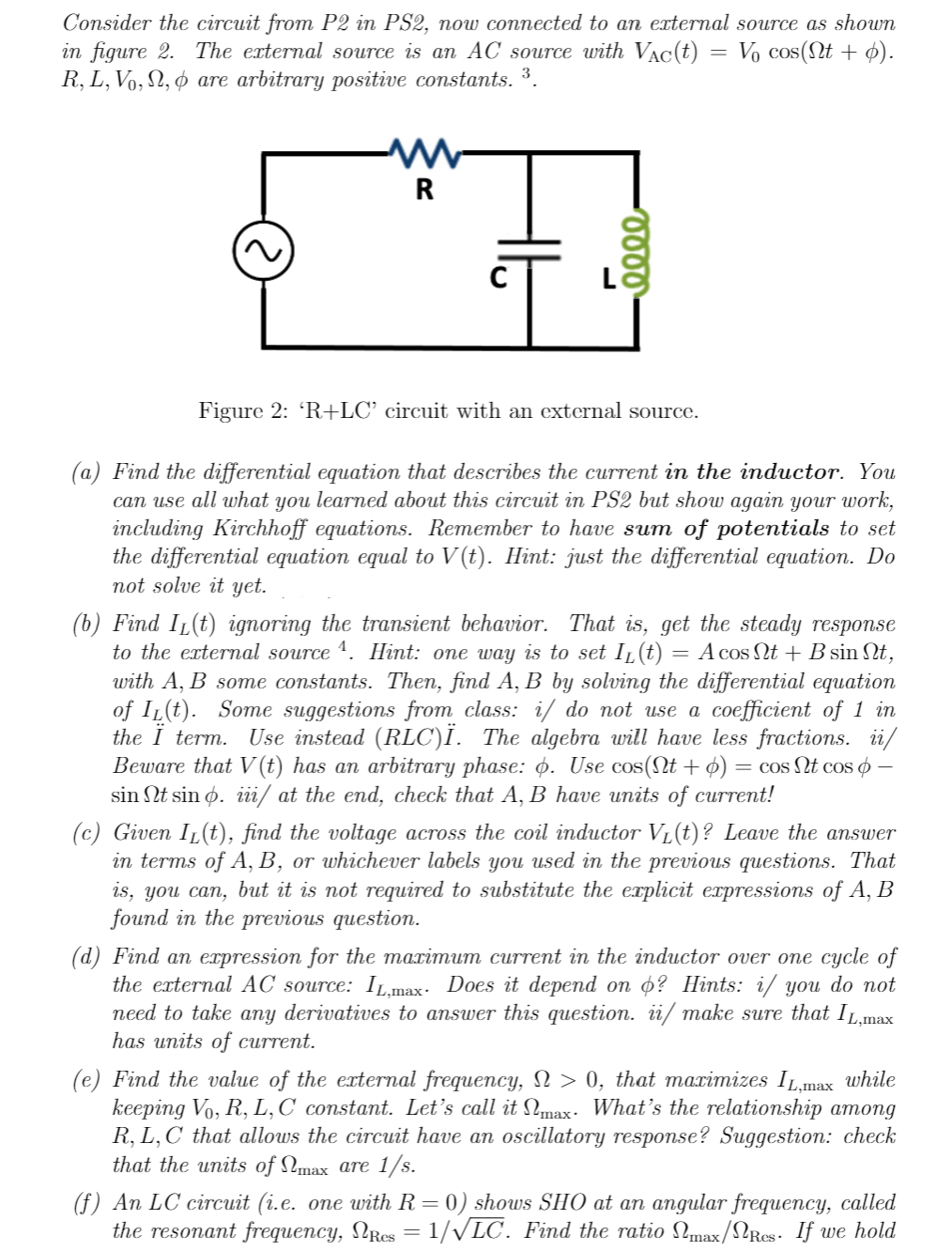
Consider the circuit from P2 in PS2, now connected to an external source as shown in figure 2. The external source is an AC source with Vac(t) = V₁ cos(Nt + p). R, L, Vo, 2, are arbitrary positive constants. ³. R HI 0000 Figure 2: 'R+LC' circuit with an external source. (a) Find the differential equation that describes the current in the inductor. You can use all what you learned about this circuit in PS2 but show again your work, including Kirchhoff equations. Remember to have sum of potentials to set the differential equation equal to V(t). Hint: just the differential equation. Do not solve it yet. (b) Find IL(t) ignoring the transient behavior. That is, get the steady response to the external source 4. Hint: one way is to set I₁(t) = A cos Nt + B sin Nt, with A, B some constants. Then, find A, B by solving the differential equation of IL(t). Some suggestions from class: i/ do not use a coefficient of 1 in the Ï term. Use instead (RLC)Ï. The algebra will have less fractions. ii/ Beware that V(t) has an arbitrary phase: p. Use cos(nt + p) = cos Nt cos - sin Nt sin o. iii/ at the end, check that A, B have units of current! (c) Given IL(t), find the voltage across the coil inductor V₁(t)? Leave the answer in terms of A, B, or whichever labels you used in the previous questions. That is, you can, but it is not required to substitute the explicit expressions of A, B found in the previous question.
Consider the circuit from P2 in PS2, now connected to an external source as shown in figure 2. The external source is an AC source with Vac(t) = V₁ cos(Nt + p). R, L, Vo, 2, are arbitrary positive constants. ³. R HI 0000 Figure 2: 'R+LC' circuit with an external source. (a) Find the differential equation that describes the current in the inductor. You can use all what you learned about this circuit in PS2 but show again your work, including Kirchhoff equations. Remember to have sum of potentials to set the differential equation equal to V(t). Hint: just the differential equation. Do not solve it yet. (b) Find IL(t) ignoring the transient behavior. That is, get the steady response to the external source 4. Hint: one way is to set I₁(t) = A cos Nt + B sin Nt, with A, B some constants. Then, find A, B by solving the differential equation of IL(t). Some suggestions from class: i/ do not use a coefficient of 1 in the Ï term. Use instead (RLC)Ï. The algebra will have less fractions. ii/ Beware that V(t) has an arbitrary phase: p. Use cos(nt + p) = cos Nt cos - sin Nt sin o. iii/ at the end, check that A, B have units of current! (c) Given IL(t), find the voltage across the coil inductor V₁(t)? Leave the answer in terms of A, B, or whichever labels you used in the previous questions. That is, you can, but it is not required to substitute the explicit expressions of A, B found in the previous question.

Introductory Circuit Analysis (13th Edition)
13th Edition
ISBN:9780133923605
Author:Robert L. Boylestad
Publisher:Robert L. Boylestad
Chapter1: Introduction
Section: Chapter Questions
Problem 1P: Visit your local library (at school or home) and describe the extent to which it provides literature...

Related questions
Question
Transcribed Image Text:Consider the circuit from P2 in PS2, now connected to an external source as shown
in figure 2. The external source is an AC source with Vac(t) Vo cos(nt + p).
R, L, Vo, №, & are arbitrary positive constants. ³.
W
R
0000
Figure 2: 'R+LC' circuit with an external source.
=
(a) Find the differential equation that describes the current in the inductor. You
can use all what you learned about this circuit in PS2 but show again your work,
including Kirchhoff equations. Remember to have sum of potentials to set
the differential equation equal to V(t). Hint: just the differential equation. Do
not solve it yet.
(b) Find IL(t) ignoring the transient behavior. That is, get the steady response
to the external source ¹. Hint: one way is to set I₁(t) = A cos Nt + B sin Nt,
with A, B some constants. Then, find A, B by solving the differential equation
of IL(t). Some suggestions from class: i/ do not use a coefficient of 1 in
the Ï term. Use instead (RLC)Ï. The algebra will have less fractions. ii/
Beware that V (t) has an arbitrary phase: Ġ. Use cos(Nt + p) : = cos Nt cos -
sin Nt sin p. iii/ at the end, check that A, B have units of current!
(c) Given I₁(t), find the voltage across the coil inductor V₁(t)? Leave the answer
in terms of A, B, or whichever labels you used in the previous questions. That
is, you can, but it is not required to substitute the explicit expressions of A, B
found in the previous question.
(d) Find an expression for the maximum current in the inductor over one cycle of
the external AC source: IL,max. Does it depend on o? Hints: i/ you do not
need to take any derivatives to answer this question. ii/ make sure that IL,max
has units of current.
(e) Find the value of the external frequency, N > 0, that maximizes IL,max while
keeping Vo, R, L, C constant. Let's call it max. What's the relationship among
R, L, C that allows the circuit have an oscillatory response? Suggestion: check
that the units of max are 1/s.
(f) An LC circuit (i.e. one with R = 0) shows SHO at an angular frequency, called
the resonant frequency, NRcs = 1/√LC. Find the ratio Nmax/Res. If we hold
Transcribed Image Text:L,C constant and vary R, do we need to increase or decrease R in order to get
max closer to Res?
Expert Solution
This question has been solved!
Explore an expertly crafted, step-by-step solution for a thorough understanding of key concepts.

This is a popular solution!

Trending now
This is a popular solution!

Step by step
Solved in 6 steps with 5 images

Knowledge Booster


Learn more about
Need a deep-dive on the concept behind this application? Look no further. Learn more about this topic, electrical-engineering and related others by exploring similar questions and additional content below.Recommended textbooks for you
Introductory Circuit Analysis (13th Edition)
Electrical Engineering
ISBN:
9780133923605
Author:
Robert L. Boylestad
Publisher:
PEARSON

Delmar's Standard Textbook Of Electricity
Electrical Engineering
ISBN:
9781337900348
Author:
Stephen L. Herman
Publisher:
Cengage Learning

Programmable Logic Controllers
Electrical Engineering
ISBN:
9780073373843
Author:
Frank D. Petruzella
Publisher:
McGraw-Hill Education
Introductory Circuit Analysis (13th Edition)
Electrical Engineering
ISBN:
9780133923605
Author:
Robert L. Boylestad
Publisher:
PEARSON
Delmar's Standard Textbook Of Electricity
Electrical Engineering
ISBN:
9781337900348
Author:
Stephen L. Herman
Publisher:
Cengage Learning
Programmable Logic Controllers
Electrical Engineering
ISBN:
9780073373843
Author:
Frank D. Petruzella
Publisher:
McGraw-Hill Education

Fundamentals of Electric Circuits
Electrical Engineering
ISBN:
9780078028229
Author:
Charles K Alexander, Matthew Sadiku
Publisher:
McGraw-Hill Education

Electric Circuits. (11th Edition)
Electrical Engineering
ISBN:
9780134746968
Author:
James W. Nilsson, Susan Riedel
Publisher:
PEARSON

Engineering Electromagnetics
Electrical Engineering
ISBN:
9780078028151
Author:
Hayt, William H. (william Hart), Jr, BUCK, John A.
Publisher:
Mcgraw-hill Education,