The switch in the circuit shown in FIGURE Q2 has been closed for a long time. At t = 0 the switch is opened. i. With the switch closed, determine the inductor's initial current, i(0) and with the switch opened, determine the inductor's final current, i(∞) and the time constant. ii. Evaluate whether the circuit is a source - free or step response circuit. Hence, determine the inductor's current, i(t) for t > 0 iii. Discuss how the values of the voltage source and resistors in the circuit, affect the inductor's current, i(t).
The switch in the circuit shown in FIGURE Q2 has been closed for a long time. At t = 0 the switch is opened. i. With the switch closed, determine the inductor's initial current, i(0) and with the switch opened, determine the inductor's final current, i(∞) and the time constant. ii. Evaluate whether the circuit is a source - free or step response circuit. Hence, determine the inductor's current, i(t) for t > 0 iii. Discuss how the values of the voltage source and resistors in the circuit, affect the inductor's current, i(t).

Electricity for Refrigeration, Heating, and Air Conditioning (MindTap Course List)
10th Edition
ISBN:9781337399128
Author:Russell E. Smith
Publisher:Russell E. Smith
Chapter4: Electric Meters
Section: Chapter Questions
Problem 23RQ: What basic concept is used in a digital meter to calculate the circuit characteristics being...

Related questions
Question
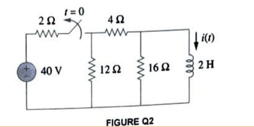
The switch in the circuit shown in FIGURE Q2 has been closed for a long time. At t = 0 the switch is opened.
i. With the switch closed, determine the inductor's initial current, i(0) and with the switch opened, determine the inductor's final current, i(∞) and the time constant.
ii. Evaluate whether the circuit is a source - free or step response circuit. Hence, determine the inductor's current, i(t) for t > 0
iii. Discuss how the values of the voltage source and resistors in the circuit, affect the inductor's current, i(t).
Transcribed Image Text:1=0
202
402
ww
ww
i(t)
40 V
1202
16 Ω
2 H
FIGURE Q2
Expert Solution
This question has been solved!
Explore an expertly crafted, step-by-step solution for a thorough understanding of key concepts.

Step by step
Solved in 3 steps with 2 images

Recommended textbooks for you
Electricity for Refrigeration, Heating, and Air C…
Mechanical Engineering
ISBN:
9781337399128
Author:
Russell E. Smith
Publisher:
Cengage Learning
Electricity for Refrigeration, Heating, and Air C…
Mechanical Engineering
ISBN:
9781337399128
Author:
Russell E. Smith
Publisher:
Cengage Learning