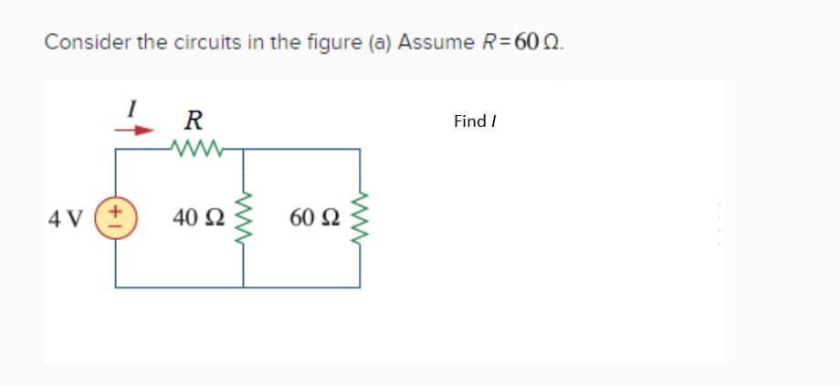
Consider the circuits in the figure (a) Assume R=600. 4V (+ R www 40 92 60 92 Find /


Q: A 200 V, d.c. shunt-wound motor has an armature resistance of 0.4 Ω and at a certain load has an…
A: Given, Voltage V=200 V Armature resistance =0.4Ω Initial current I1=30 A Final current I2=45 A
Q: + li 0.5Ω m لشها if C wwww 5923 m m ев 492 10Ω wwww www 292 wwww 1 + eo
A:
Q: An underground cable has the following primary constants: resistance R = 10/loop km, inductance L =…
A: Resistance R = 10Ω Inductance L = 1.5 mH Conductance G = 1.2μS Capacitance C = 0.06μF
Q: Q2) Using the nodal analysis, find the node voltages V₁ and V₂, then find the power dissipated in…
A:
Q: For the circuit shown in the figure, the Thevenin voltage (Vth) at terminals a-b is: 492 ww 502 O a.…
A:
Q: 13). A motor with power factor of 0.85 is served by a single- phase 120 V source; the motor requires…
A: In this question we need to find a efficiency of motor and line current drawn by the motor.
Q: Find V. 6ΚΩ Ο 14,4V Ο 1661 Ο 15.5 1 Ο 13.3 V 21χ + υ 24 mA ( A 32 ΚΩ
A:
Q: The magnetic field set up in the iron core of a transformer comes from the (A) active B) reactive…
A: Transformers are supplied with ac voltage on the primary side Transformers doesn't work with dc…
Q: a 120v dc shunt motor has an armature resistance of 0.25 ohms is drawing 50a. if a fixed loss of…
A: In this question, We need to determine the break horse power of the DC shunt motor. We know 1HP=…
Q: Q2: For a (3-0) medium transmission line model (T cct) as shown in next figure, find the, current…
A: Given parameters are:…
Q: 1. Find the transfer function, G(s) = vi(t) 1+ 1 H oooo 1 H Vo(s) V{(s) 1 H oooo for the given…
A:
Q: in the ujt and scr connection, why is that the scr remains off when the ujt is firing? maybe in the…
A: It is asked the reason for which that the SCR remains off when the UJT is firing.
Q: 37. What are the frequencies just above the EHF range called? 38. What is a micrometer, and what is…
A:
Q: In a basic block diagram, where is summing point usually located? Near the reference input Near the…
A: The summing point is located after the reference input and before the controller transfer function.…
Q: Q2: For a (3-0) medium transmission line model (T cct) as shown in next figure, find the, current…
A: Given: Sending End Voltage Vs = 247.4∠23.3 kv/phaseSending End Current Is = 603.5∠-10.27∘ ampSeries…
Q: Q5) Find the Thevenin equivalent circuit for the network in Fig. 5. Then, under the maximum power…
A:
Q: 4. Unless the state of a NAND gate latch is being change, its inputs should both be b. low a. high…
A:
Q: The distribution factor for 90 slots, 10-pole, 3-phase winding is A 0.90 B C D 0.895 0.959 0.978
A: Given: A 3-phase winding machine with, Slots = 90. Pole = 10.
Q: A) Write Matlab codes to plot the function y for -5 ≤ x ≤5 with 0.1 interval. -&₁ x > 0 x = 0 0 1 x…
A: Given, Using MATLAB plot below function -5 <= x <= 5 y = 1 ; x>0 = 0; x= 0 = -1;…
Q: For the network shown in Fig. determine the following a) Ing b) Ice) VCEod) Vc e) VB
A:
Q: Determine VI and V₂ using nodal analysis V₁ 5012 V2 5A1 400 3029A
A: We need to find out node voltage for given circuit by using of nodal analysis .
Q: Q4) Find the Norton equivalent circuit for the portions of the networks of Fig. 4 external to branch…
A:
Q: 1. What is an electric field line? What are equipotential surfaces? Are they necessarily physical…
A: 1). Electric field line: An electric field line is an imaginary line or curve drawn through a…
Q: Q.5: Determine the inductor current for t<0 for circuit in Figure. 25 V 392 1=0 292 4 H
A: Given, The circuit is,
Q: 10. Detemine the betwween a an b points Va , when R= 30 2 (Fig.1) a Fig.1 50 V 130 V AI 202 100…
A: We are authorized to answer one question at a time, since you have not mentioned which question you…
Q: The continuous, sinusoidal varying voltage v(t) or alternating current i(t) available from an…
A:
Q: Ex Design a colpitts oscillator to oscillate at 100 KHZ, use L= 0ilm H and the gain must be not…
A: Given: Frequency is 100 kHz
Q: The following information is given for a 100kW, 400 V, short shunt compound generator: Shunt field…
A:
Q: Determine the Laplace transform using integral of the following equations. 1. e^-at u(t) 2. tu(t)
A: It is given that: 1.e-atu(t)2.tu(t)
Q: Given the empirical diode junction equation V = nV, In with VT = 26 mV, Is = 3.9x10⁻¹⁵ A. Determine…
A: Given, Diode voltage VD=nVTlnIDIs VT=26 mV Supply current Is=3.9×10⁻¹⁵ A
Q: 1. Determine all the mesh currents using mesh analysis. Show complete solution using either…
A: In this question we need to find a mesh current of the given circuit.
Q: 5 kN 7 kN 30° 70° 1. Assuming the resultant force is zero, if F₂= 6 kN, determine the magnitude of…
A:
Q: 5. Build a simple circuit where an LED is controlled by a transistor. Use appropriate resistance.…
A:
Q: I1 2 T R2 30. 20 R3 40. il 12 1
A:
Q: When a forward voltage of 0.4V is applied to a silicon diode, the forward current is 10mA. Find the…
A: Given : ID=10 mAVD=0.4Vη=2VT=T11600=29311600=0.02526 V
Q: 4.14. Consider a four-pole AC machine. Calculate the supply frequency in Hz from an inverter which…
A: Given, An AC machine has, Number of poles, P=4. Synchronous speed, Ns=18 krpm.
Q: Find Id and Vd from the circuit given below. The JFET is a 2N4416 with Idss = 10 mA and Vp = -3 V.…
A:
Q: 8.42 The voltage across an impedance Zis 100/15° and the current through Z is 202-45° A. The active…
A: Given, Voltage across impedance, V=100∠15° V. Current through impedance, I=20∠-45° A.
Q: Q4) Find the Norton equivalent circuit for the portions of the networks of Fig. 4 external to branch…
A: A circuit is represented by its equivalent Thevnin's circuit or Norton's circuit. In Thevenin…
Q: Q5) In the circuit, shown in Fig. 5 determine the value of E so that the current 1-0. Use mesh…
A:
Q: 18V- 9Ω www. 8Ω Μ 12Ω 18Ω 11Ω www 5Ω ΖΩΙ ΜΕ ΠΩ 3Ω Μ ΠΩ ΕΣΤΩ 5Ω
A:
Q: 1. Write the differential equation of the following function. s³+4s²+25+2 s²+2s²+1 1. write the…
A:
Q: 4. Determine V₁1 and V₂ using nodal analysis. Show complete solution using either elimination…
A:
Q: Using Gauss’ law deduce the expression for the electric field due to a uniformly charged spherical…
A: Electric Field:- Each point in space has an electric characteristic whenever a charge of any kind is…
Q: Under uniform field conditions and standard atmospheric conditions, a test to determine the…
A: The breakdown strength of air is to be found for: (a) small gaps of 2 mm (b) large gaps of 15 cm The…
Q: lin Ас current_ VDD Tout ( Bias Ckt omitted here) Unity Gain Frequency f₁ = SSEC Tin | Tout | = |…
A:
Q: Determine the modulation index mf, of an FM signal which is being broadcast in the 88-108 MHz band.…
A: Carrier swing = 125 kHz Broadcasting frequency = 88 - 108 MHz
Q: 1. Explain the operation of clippers circuit. 2. List at least 3 applications of waveshaping…
A: 1) Clipper circuit: Electronic circuits known as clipper circuits eliminate a piece of an AC signal…
Q: 12. Draw the Timing diagram for INR M. > Fetching the Opcode 34 from the memory 4105H. > Let the…
A: INR M: The content of the memory location addressed by the H-L pair is incremented by one.…
Q: Q1) Find the Thevenin equivalent circuit for the network in the shaded area of Fig 1. Then, find the…
A:

Step by step
Solved in 2 steps with 1 images


- Draw the below-given circuit. Change the value of components and add RL as a variable resistor. Use an ammeter to measure the current for various values of RL. Verify the Maximum Power Transfer theorem using the circuit below. Vth = 25 Volts and Rth = 140 Ohms.part a = 628.57 rad/sec part b R = 338.5 Ω part c see circuit below Need help with parts d, e, f, and g. Thank you.i need perfect answer....and i will rate Determine the value of V0 using source transformation in the below figure.
- For the circuit shown in the figure above, what is the equivalent resistance Req as seen from the a-b terminals? Assume R1 = 83 , R2 = 55 , and R3 = 91If you calculate the values for a Thevenin equivalent circuit as VTH = 12.34V and RTH = 8.77kΩ. What is the value of load resistor that will produce the maximum load power possible. a 1.41mΩ b 108.2kΩ c 12.34Ω d 8.77kΩIn the circuit given below, R = 40 Ω. Calculate v1 and v2.
- With the following FET Calculate VD and VS by doing DC analysis of the circuit.? VGS (Th) = 4 V, k = 0.45x10⁻³ A / V2 (Note: Whether graphical with analysis or with mathematical (analytical) analysis you can calculate.)If the circuit in figure has a value of Vi1 = 3V; Vi2 = 4V; Ri1 = Ri2 = Ro1 = Ro2 = 1K, determine the value of V output (Vo)!Create a schematics Multi-mode power supply (just like computer power supply size) with the choices of 5volts, 9volts and 12volts, and 2Ampere
- A moving coil ammeter gives a full scale deflection for a current i = 250 mA and its coil has a resistance RC = 0.75 Ω. It is provided with a multiplier resistance Rm that allows a voltage measurement of up to 5 V. What is the value of the multiplier resistance? Select one: a. 2.0 Ω b. 19.25 Ω c. 0.5 Ω d. 20.75 Ω1.a. What circuit is shown on the image above? 1.b. What is the gain? 1.c. If R2 is 40x higher than R1 what will happen to node 2? Provide waveform and explain why it happens. 1.d. Modify the circuit to have an overall gain of 2. Provide photos.In the circuit in Figure 1, Find the value v0 using Thevenin's Theorem.