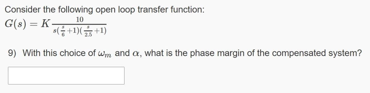
Consider the following open loop transfer function: 10 G(s) = K- %3D 2.5 9) With this choice of wm and a, what is the phase margin of the compensated system?


Q: The asymptotic gain-frequency characteristic of a system is shown in FIGURE . Assess the transfer…
A: Minimum phase system does not contain any poles and zeros on the right side of imaginary axis.
Q: Q.8: Design a component values for RLC series circuit with center frequency of 20KHZ and quality…
A: The solution for the given problem is given below and corner frequencies ae also solved.
Q: a. Determine r.. b. Find A, = Vo/Vi- c. Calculate Z;. d. Determine fLsfLe e. Determine the low…
A: Brief description : In the above given question they have mentioned a common collector amplifier…
Q: Determine the closed loop transfer function of the given system. Choose the answer from below…
A: The above question is based on finding transfer function using block reduction technique. Transfer…
Q: Vcc +9 V Bpc = Bac = 125 Che = 25 pF Che = 10 pF Rc 220 Ω Determine the critical frequencies…
A: Given data, βDC=125βac=125Cbe=25 pFCbc=10 pFRC=220 ΩRE=100 ΩC1=1 μFC2=10 μFC3=1 μFRL=680 ΩR1=12…
Q: 4.3 Home work 1- In the circuit that shown in Figure 4.1. Prove that V1=Q.V at resonance frequency.…
A: Since you have asked multiple questions in a single request, we will be answering only the 1st…
Q: se complex impedance notation to find the expression for the frequency response function…
A:
Q: DISCUSSION: 1- Is the concept of resonance limited to electrical or electronic systems. 2- Define…
A: Solution : Note: It is the kind notice that according to the guidelines of the company we have to…
Q: 6. Derive the closed loop transfer function from R to X for the following system R A(s) C(s) B(s) X
A: Given a control system block diagram Find loop transfer function
Q: Si If A(s): = + Se Sfb 200 (1+²)(1+ So A(s) F and F = 0.3, solve the following: S 10000,
A: This problem can be done by finding magnitude of loop transfer function at unity and finding phase…
Q: Design an active high-pass filter circuit using op-amp and calculate the value of the capacitor,…
A: It is given that: fc=331Hz
Q: (i) Show that Ic = 2.8mA. (ii) Draw and label the small-signal hybrid-r equivalent circuit at middle…
A:
Q: Q4. Suppose the circuit shown has the given characteristics at resonance. Determine: a) the value of…
A: We need to analyse the parallel resonance circuit , we need to calculate R and L value form given…
Q: The bode plot is a standard approach to feedback control systems analysis and design. The transfer…
A: A system's transfer function is defined as the ratio of the output Laplace transform to the input…
Q: Determine the I0(s) / Ii(s) transfer function for the circuit given in the figure.
A:
Q: bessel bandpass filter analysis and all formula. lecture summary
A: Bessel bandpass filter analysis is as follows: Bessel filter is a sort of simple straight channel…
Q: A coil of resistance 20hms and inductance 200uH is in parallel with a variable capacitor. The…
A: The value of capacitor can be calculated by using the frequency of resonance and the current can be…
Q: Feedback and Control Systems Using mesh and nodal analysis, find the transfer function G(s) = Vo(s)…
A:
Q: Question 6 Consider a closed-loop control with the following loop transfer function: 1 L(s) =…
A: Brief description: From the given bode plots we need to justify stability of the system.
Q: Find the transfer function for the circuit shown in the figure. Plot the amplitude graph of…
A:
Q: 3) factor Q= 10 and break frequency fo = 1 kHz. Component values need not be standard, but as always…
A:
Q: Calculate the complex transfer function of the circuit. Write down expressions for the frequency…
A: Given circuit-
Q: A 100 kVA, 50 Hz, 230/50 kV testing transformer has an 8% leakage reactance and a 2% winding…
A: It is given that: Transformer rating:100KVAVoltage ratio:23050kVFrequency:F=50HzR=0.2%X=0.8%
Q: Q9. The specifications of a tuned amplifier are as follows. Voltage gain = 12, VCE = 7V, B =75, Ie…
A: The detailed answer is solved below according to the given parameters and instructions in the…
Q: CMI + Cgs = (1+gm(r,l|RpL))Cgd + Cgs, so C, is clearly >> %3D Cgd. This means that fol << f» since…
A:
Q: For the control system shown on: a. Draw the Bode diagram for the open-loop system for K=500.…
A: According to question: a) The gain in [dB] and phase of the open loop transfer function is…
Q: Question 2: The schematic diagram of a circuit is shown in the figure below. As you consists of…
A: As the given circuit is divided into three parts
Q: For the system given in figure below, the transfer function C(s)/ U(s) is
A:
Q: Q1: For the open loop poles shown in figure s-plane 1- Find the open loop transfer function 2-…
A:
Q: . Suppose a circuit has a transfer function of the form A(ω)=A0[1-(jω/ω0)]. For A0=100 V/V and…
A: In this question, Suppose a circuit has a transfer function of the form A(ω)=A0[1-(jω/ω0)]. For…
Q: For the circuit in the figure, assuming that the op-amp is ideal in all respects: 1. Derive an…
A:
Q: B- For the open-loop transfer function, maximum overshoot, and settling time. 110 (s+4)(0.2s+10)…
A:
Q: 1. a) Using the relationship between the bandwidth and the cutoff frequencies and the relationship…
A: (a) Write the expression for the bandwidth in terms of the cut-off frequencies. 2πβ=ωc2-ωc1…
Q: ut-output trallsiel Tunc entirely different set of terminologies and definitions than those of…
A: This is a simple question based on control system subject. In this we have to determine the signal…
Q: a) The open loop transfer function of a discrete-time system is given by k (z+0.9) G (Z) =…
A: The open loop transfer function of a discrete-time system is given by G(z) = k (z+0.9)/…
Q: Which of the following method is used to find the stability of closed loop system without finding…
A: Root locus method requires poles and zeros location of open loop system.
Q: (b) The crossover frequency in the figure shown below is a low pass filter that is connected to a…
A: The circuit is shown below: Applying K.C.L at node 1 of the above circuit,…
Q: Q5 A unity feedback control system has open loop transfer function: 2 G(s) = s(1+ 0.5s)(1+ 0.05s)…
A:
Q: i. What order and type of filter is this? Shortly explain. ii. Derive the transfer function, H(f),…
A: Given figure Here R=120 Ω,L=15 mH=15×10-3 H,C=2 μF=2×10⁻⁶ F. Vin is the input voltage and Vout is…
Q: Q4. Suppose the circuit shown has the given characteristics at resonance. Determine: a) the value of…
A:
Q: 3. Consider the following closed-loop Transfer function. Determine the range for K for the system to…
A: As per our company guidelines we are supposed to answer only first sub parts. Kindly repost other…
Q: Given R1 = R2 = 100 Q and L = 2 mH. Based on the circuit in Figure A, i) ii) iii) Obtain the…
A:
Q: Analyze how the impedance of the circuit changes when the input signal frequency changes from 0 to…
A: To solve the above problem, one should have a basic idea about the working of AC circuits. In AC…
Q: 752. See Figure 752. D=5. The Bode gain and phase plots for a RC circuit are shown in the fig.…
A:
Q: a) i. How to identify the system's stability using frequency domain technique? ii. Normalised the…
A: The answer as given below:
Q: = (4) A feedback system has the loop transfer function (s)H(s) 20(s+0.1)/[s(s+4)(s+8)]. Determine…
A: Given, Transfer function G(s)H(s)=20(s+0.1)/[s(s+4)(s+8)]. In this question corner frequencies and…
Q: Problem 4. Consider a system with the following open – loop transfer function 2 G(s) =- s(0.3s…
A: Consider the following open-loop transfer function The characteristic equation is The zeroes of…
Q: Q-factor and bandwidth
A: Resistance in parallel- 1/Req=1/R1+1/R2+1/R3+........... Resistance in series-…
Q: Gain Phase deg dB Ph 10w, 2= integrator
A:
Q: Which of the following method is used to find the stability of closed loop system without finding…
A: to find which method is used to find the stability of closed loop system without finding the roots…

Step by step
Solved in 2 steps with 3 images

- Which of the following method is used to find the stability of closed loop system without finding the roots of the closed loop system? a-Bode Plot b-Root Locus Method c-Nyquist Stability Criterion d-Routh Hurwitz CriterionExampleUnder clear-sky conditions, the downlink[C/N] is 20 dB, the effective noise temperatureof the receiving system being 400 K. if the rainattenuation is 1.9 dB, calculate the new [C/N].Assume the medium temperature of 290K andthe coupling coefficient is 100%.i) Which type of compensator is used for feeding reactive power at the receiving end? Draw its block diagram. (ii) What is lag-lead compensator? Draw its circuit diagram and derive the expression for the transfer function of lag-lead compensator.
- Using Thevenin and Norton Theorem, calculate the theoretical values of RTH, RN, Voc, and IscThis is about two points, (x1,y1) and (x2,y2), on a straight line whose slope is given in dB/decade. The x-axis is log and the y-axis is linear. Find y2 in dB given: y1=35 dB, x1=20, x2=23, slope=63 dB/decade.What is the bandwidth of the system?
- 1. You are given an equation: 100 cos[(2π×10^5t) + 35 cos(100πt)]. From this expression, Determine the: a)peak frequency deviation b) carrier swing c)practical bandwidth d) Carson’s rule bandwidth Please put the corresponding item(letters a-d) to categorize the answers/solution.Suppose the noise power at the input to a receiver is 5 nW in the bandwidth of interest. What would be the required signal power for signal–to–noise ratio of 30 dB? full solution thank you for the help!An impedance coil having a resistance of 30 ohms and a 50 cps inductive reactance of 33.3 ohmsis connected to a 125 volt 60 cps source. A series circuit consisting of a 20 ohm resistor and avariable capacitor is then connected in parallel with the coil. (a) for what values of capacitancewill the circuit be in resonance? (b) calculate the two values of line current for the condition ofresonance.