Consider the full-wave rectifier circuit below. RL= 10 kS, V₁ = 0.7V, the input voltage V₁ = 120sin(2 60t) V(rms). The transformer turns ratio ₁ = 20, where N₁ is the number of N₂ turns in the primary and N₂ is the number of turns in each of the secondary winding. a) Plot Vs and Vo on the same graph for two periods, assuming there is no capacitor (C = 0). b) Determine the capacitor value so that the ripple voltage is limited to 1V. Plot the output voltage on the graph from part a) c) Indicate on the graph where diode D₂ has the maximum reverse bias and determine Peak Inverse Voltage (PIV). D1
Consider the full-wave rectifier circuit below. RL= 10 kS, V₁ = 0.7V, the input voltage V₁ = 120sin(2 60t) V(rms). The transformer turns ratio ₁ = 20, where N₁ is the number of N₂ turns in the primary and N₂ is the number of turns in each of the secondary winding. a) Plot Vs and Vo on the same graph for two periods, assuming there is no capacitor (C = 0). b) Determine the capacitor value so that the ripple voltage is limited to 1V. Plot the output voltage on the graph from part a) c) Indicate on the graph where diode D₂ has the maximum reverse bias and determine Peak Inverse Voltage (PIV). D1

Introductory Circuit Analysis (13th Edition)
13th Edition
ISBN:9780133923605
Author:Robert L. Boylestad
Publisher:Robert L. Boylestad
Chapter1: Introduction
Section: Chapter Questions
Problem 1P: Visit your local library (at school or home) and describe the extent to which it provides literature...

Related questions

Question
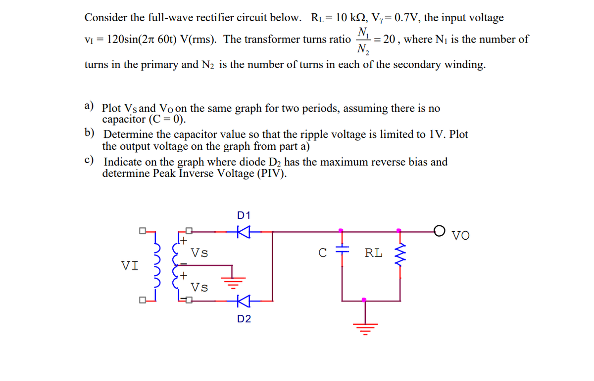
Transcribed Image Text:Consider the full-wave rectifier circuit below. RL = 10 kQ, Vy= 0.7V, the input voltage
N₁
V₁ = 120sin(2 60t) V(rms). The transformer turns ratio = 20, where N₁ is the number of
N₂
turns in the primary and N₂ is the number of turns in each of the secondary winding.
a) Plot Vs and Vo on the same graph for two periods, assuming there is no
capacitor (C = 0).
b) Determine the capacitor value so that the ripple voltage is limited to 1V. Plot
the output voltage on the graph from part a)
c)
Indicate on the graph where diode D₂ has the maximum reverse bias and
determine Peak Inverse Voltage (PIV).
VI
Vs
Vs
D1
KH
KH
D2
с
RL
VO
Expert Solution
This question has been solved!
Explore an expertly crafted, step-by-step solution for a thorough understanding of key concepts.

Step by step
Solved in 5 steps with 6 images

Knowledge Booster


Learn more about
Need a deep-dive on the concept behind this application? Look no further. Learn more about this topic, electrical-engineering and related others by exploring similar questions and additional content below.Recommended textbooks for you
Introductory Circuit Analysis (13th Edition)
Electrical Engineering
ISBN:
9780133923605
Author:
Robert L. Boylestad
Publisher:
PEARSON

Delmar's Standard Textbook Of Electricity
Electrical Engineering
ISBN:
9781337900348
Author:
Stephen L. Herman
Publisher:
Cengage Learning

Programmable Logic Controllers
Electrical Engineering
ISBN:
9780073373843
Author:
Frank D. Petruzella
Publisher:
McGraw-Hill Education
Introductory Circuit Analysis (13th Edition)
Electrical Engineering
ISBN:
9780133923605
Author:
Robert L. Boylestad
Publisher:
PEARSON
Delmar's Standard Textbook Of Electricity
Electrical Engineering
ISBN:
9781337900348
Author:
Stephen L. Herman
Publisher:
Cengage Learning
Programmable Logic Controllers
Electrical Engineering
ISBN:
9780073373843
Author:
Frank D. Petruzella
Publisher:
McGraw-Hill Education

Fundamentals of Electric Circuits
Electrical Engineering
ISBN:
9780078028229
Author:
Charles K Alexander, Matthew Sadiku
Publisher:
McGraw-Hill Education

Electric Circuits. (11th Edition)
Electrical Engineering
ISBN:
9780134746968
Author:
James W. Nilsson, Susan Riedel
Publisher:
PEARSON

Engineering Electromagnetics
Electrical Engineering
ISBN:
9780078028151
Author:
Hayt, William H. (william Hart), Jr, BUCK, John A.
Publisher:
Mcgraw-hill Education,