Consider the pipe assembly in the Figure below. The applied forces are defined as F1 = (100i -120j +75k) kN and F2= (-200i +250j +100k) kN 1. Determine the resultant force vector F in kN. 2. Determine the position vector roA in m. 3. Determine the moment of the forces Mo about point O in kNm. Express all the results in vectorial form referring to the coordinate system given in the figure. Note that the x-,y-,z-axis positive direction is towards the respective letters.
Consider the pipe assembly in the Figure below. The applied forces are defined as F1 = (100i -120j +75k) kN and F2= (-200i +250j +100k) kN 1. Determine the resultant force vector F in kN. 2. Determine the position vector roA in m. 3. Determine the moment of the forces Mo about point O in kNm. Express all the results in vectorial form referring to the coordinate system given in the figure. Note that the x-,y-,z-axis positive direction is towards the respective letters.

Related questions
Question
B6
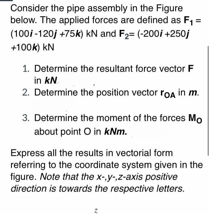
Transcribed Image Text:Consider the pipe assembly in the Figure
below. The applied forces are defined as F1 =
(100i -120j +75k) kN and F2= (-200i +250j
+100k) kN
1. Determine the resultant force vector F
in kN.
2. Determine the position vector roA in m.
3. Determine the moment of the forces Mo
about point O in kNm.
Express all the results in vectorial form
referring to the coordinate system given in the
figure. Note that the x-,y-,z-axis positive
direction is towards the respective letters.
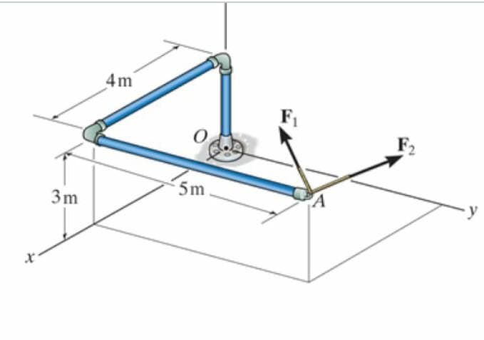
Transcribed Image Text:4m
F2
5m
3m
Expert Solution
This question has been solved!
Explore an expertly crafted, step-by-step solution for a thorough understanding of key concepts.

This is a popular solution!

Trending now
This is a popular solution!

Step by step
Solved in 4 steps with 3 images
