Considering the Following Circuk with an ideal OP AMP. 1-Find vo whenvt-2v. va4v RI 2ko. R2 10ka. R 0. R 10O? R2 R1 Ut V1 Vo R3 V2 R4 10k 741
Considering the Following Circuk with an ideal OP AMP. 1-Find vo whenvt-2v. va4v RI 2ko. R2 10ka. R 0. R 10O? R2 R1 Ut V1 Vo R3 V2 R4 10k 741

Delmar's Standard Textbook Of Electricity
7th Edition
ISBN:9781337900348
Author:Stephen L. Herman
Publisher:Stephen L. Herman
Chapter18: Resistive-inductive Parallel Circuits
Section: Chapter Questions
Problem 13PP: In an R-L parallel circuit, IT=1.25 amps, R=1.2k, and XL=1k. Find IR

Related questions
Question
Please provide Handwritten answer.
Find V0?
V1= 2V
V2= 4V
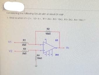
Transcribed Image Text:Considering the Following Circuk with an ideal OP-A.
1-Find vo when vt-2v. v24v. R1 2ko. R2 10ka. R3 2o. R4 10kO7
R2
R1
ut
Vi
Vo
R3
V2
2kn
R4
10kn
741
Expert Solution
This question has been solved!
Explore an expertly crafted, step-by-step solution for a thorough understanding of key concepts.

Step by step
Solved in 2 steps with 1 images

Knowledge Booster


Learn more about
Need a deep-dive on the concept behind this application? Look no further. Learn more about this topic, electrical-engineering and related others by exploring similar questions and additional content below.Recommended textbooks for you
Delmar's Standard Textbook Of Electricity
Electrical Engineering
ISBN:
9781337900348
Author:
Stephen L. Herman
Publisher:
Cengage Learning
Delmar's Standard Textbook Of Electricity
Electrical Engineering
ISBN:
9781337900348
Author:
Stephen L. Herman
Publisher:
Cengage Learning