Construct the circuit in the schematic SV 1K 5V w 1K What logic function is performed by this circuit? Explain.
Q: An inductor designed with 400 turns coil wound on an iron core of 16 cm² cross sectional area and…
A: Given values, Number of turns, N=400Area, A=16 cm2=16×10-4 m2Length, l=1 mm=1×10⁻³ mVoltage, V=230…
Q: Determine Q-point for the diodes in the circuit given below using the constant voltage drop model…
A:
Q: Design a collector feedback bias circuit to get the Q point ICQ = 1mA and VCEQ = 6V
A: Given,For the collector feedback bias circuit,ICQ = 1mA,and,VCEQ = 6V.
Q: " A Si photodetector responds to an optical signal at 850 nm of 2 mW power with a photocurrent of…
A: Given- A Si photodetector- Optical signal at 850 nm, 2 mW power, Photocurrent = 400 μA, To Find- The…
Q: When Vin = +5V, solve for voltage across R in figure a. Use approximate diode model. +5V N -5V HI.…
A:
Q: The voltage v(t) shown in Fig. P7.85a is given by the graph shown in Fig. P7.85b. If iL(0) = 0A, how…
A:
Q: The angles of asymptotes of the root loci of the equation s3+5s2+(K+2)s+K=0 ar
A: Root loci of the equation s3 + 5s2 + (K + 2)s + K = 0 We have to find angle of asymptotes.
Q: Write a difference equation that characterizes a system whose frequency response is H(el) =…
A:
Q: Figure 2 shows an input interfacing circuit. By using your own words, explain how it works. Switch…
A: it us asked to explain the given circuit
Q: 11 USE NODAL ANALYSIS Given a = 10, b=4, c = 2, d = 2, e = 4,f=1, g = 3 and h = 2, in the circuit…
A: The required parameter can be calculated by finding the node voltage using nodal analysis. The node…
Q: Question No. 25 A three-phase, three-stack, variable reluctance step motor has 20 poles on each…
A: Given- A three-phase, variable reluctance step motor has, Number of stack, m = 3 Number of rotor…
Q: Solve for current (in uA) through R when Vin = 5V. Use Figure a. +5V -5V (a) R 4.7ΚΩ +50V -50V (b) R…
A:
Q: 6. If a 100V DC battery supplies a resistor and an uncharged capacitor, determine the voltage across…
A:
Q: Calculate the active power P, reactive power Q, apparent power S and it's phase-shift angle o…
A: Given: I=17.3-28.1j Ain polar form,I=32.998∠-58.831° AU=120.7+23.1j Vin polar form,U=122.891∠10.834°…
Q: Output voltage of an inverter is controlled by multiple pulse modulation technique. If the peak…
A:
Q: Question-1 1 Consider the following circuit where l (t) = 5e-³ sin(2t) u(t) A. R In 1) Lin C [PL.la…
A: The output voltage is given in s domain and the same can be converted into time domain by using the…
Q: 1. Using Series-Parallel concept, Find the following for the given circuit. The value of the power…
A: Given
Q: u [V] 110- 55+ 3 RMS value of the current: M 6 9 a) RMS value of the current: u(t) b) voltage u(t)…
A: In this given question , we need to find out average and RMS value of current (2 decimal place)…
Q: Q5) a) For ideal diodes, show the voltage waveforms across the secondary winding and across RL when…
A: In this question we need to draw the waveform of Vsec and Vload of the given center tapped…
Q: Assume the switch is closed at t = 0, and for t < 0, iz(t) = 0. a. Find a differential equation…
A: The differential equations for the circuit can be obtained by applying kirchhoff's current law to…
Q: QUESTION. Use loop analysis to calculate the power supplied by the 20 V source. 20 Ω · 5Ω 5Ω Ο 20 10…
A:
Q: 7 Is 12 V RT, GT 1₁ R₁ 2.2 ΚΩ 12 R₂ 4.7 k For the network above a. Find the total conductance and…
A:
Q: 8-1. Find the output of the ideal operational amplifier shown in Figure 8-28 for each of the…
A: In this question We need to determine the output voltage of the op amplifier. We know Relationship…
Q: What is the average value of the output of the half-wave rectified waveform shown? ^^^ s 100 V-
A: Calculation of average value of the output of the half wave rectifier waveform given: From the…
Q: Find total load power Provide answer asap. I will rate Positively
A: Since the given circuit is balance we can analysis the 3phase circuit on phase basis. Now we draw…
Q: acitance of a conducting sphere with radius a surrounded by a thick conducting spherical shell with…
A: In this question we need to find the capacitance of the conducting sphere.
Q: S, L $₂ L₁ S. S₂ Sa Redraw this circuit using Ladder Diagram Redraw this circuit using Ladder…
A: Three circuit diagrams are given and it is asked to redraw the circuits using Ladder Diagram.
Q: Problem 1. Consider circuit below utilizing BJTs with ß = 100 and VA = ∞. Vcc= VEE = 5 V, Io = 0.5…
A:
Q: 5) An amplitude-modulated signal is given by PAM (t) = 4[a + 2 sin(wmt)] cos(wet), where Wm << wc.…
A:
Q: (5) Over what band of frequencies will a 100 MHz carrier modulated at 5 kHz extend?
A:
Q: maximum power
A:
Q: [PI.la & Pl.1c] Find V (t), if the voltage V (s) : = 3s+10 (s+4)(s+5)
A: The output voltage is given in s domain and the same can be converted into time domain by using the…
Q: 1.3 A single-phase AC generator feeds a load. The generator may be modeled as an ideal sinusoidal…
A: In this question we need to draw and label the circuit, write down governing equations and draw the…
Q: At a frequency of 1MHz, how long is the transmission line as a fraction of a wavelength. Is the line…
A:
Q: continued fraction expansion
A:
Q: 5ΚΩ 2.5ΚΩ Μ 2mA 1+ 2.5ΚΩ www 25ΚΩ 15ΚΩ 12V a 9 b 24ΚΩ ( Τ 6mA
A: We need to find out the equivalent resistance for given circuit.
Q: 1. If G1 and G2 are in series, the equivalent transfer function is equal to (a) 61/62 (b) G1+62 (c)…
A: Given, The transfer functions G1 and G2 are connected in series in a block diagram.
Q: 6. Label each element of the circuit diagram [by the number]. What type of circuit is depicted in…
A: Solution: Given circuit:
Q: A R1 +10V lili RL 60
A:
Q: Is a semiconductor a good example to illustrate the contrast between a conductor and an insulator?…
A: Answer : Conductors are materials that allow electricity to flow freely through them, while…
Q: 6) For the circuit, find il, i2, i3 to 14 2Ω κα 5A τη 6Ω www 3% 4Ω ΑΜΕ 8Ω Ω 292 10 V
A: A supply voltage source of 10 V is applied across the left peripheral of the circuit. A current…
Q: Q₁/ A 3-phase, 11 kv, 1.2 MVA, S.G its star connected- armature winding has effective resistance of…
A:
Q: If a voltage waveform has a peak voltage of 88.0V and 4.5% ripple, what is the minimum voltage
A: In this question we need to find the minimum voltage.
Q: Drive an equation for linear signal conditioning that will convert a sensor output voltage in the…
A: I have written this solution as handwritten solution. Hope you find the solution clear.
Q: The frequency of this voltage source is V(mV) 238 136 سة 34 10 Hz 20 Hz 50 Hz 60 Hz 20t(ms)
A:
Q: Complete the timing diagram of the circuit shown below: clk D E cik clrn D Q Q clrn D 19 zzzz
A:
Q: Using a charging or discharging capacitor, define displacement current and briefly describe…
A: According to the question, using a charging or discharging capacitor, define displacement current…
Q: Compute the reactance of the following... a. 5 µF capacitor at 50 Hz b. 5 µF capacitor at 100…
A:
Q: Consider the inverting amplifier shown in Figure 1). The do signal source has a value of 400 mV. The…
A: It is given that: vs=vin=400 mVRin=500 kΩRo=5 kΩAoL=300000
Q: Solve i) and ii) and show all the steps in detail with the sketch
A: Given, The circuit diagram is shown below, Here,FA,B,C,D = ACD¯+AB¯+CD+ABC.
Please help me with the questions b
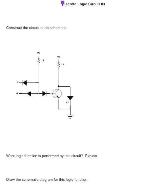
Step by step
Solved in 5 steps with 5 images
- Draw the logic circuit in the following figure?Is the truth table for below logic circuit 1,1,1,0 1) Draw a schematic diagram for the circuit 2) What logic functions is performed by this circuit? Explain?Draw a logic diagram for part a and simplify the Boolean expression in part (a) using a karnaugh map for part b. The picture contains more details of the question.
- Binary Subtractors 1. What are binary subtractors? 2. How does it work? 3. Types of binary subtractors. 4. Draw the logic circuit diagram. 5. Show the truth table. (Our subject is logic circuit and switching theory, and our lesson is combination logic circuit)Which logic circuit consisting of two inputs single output logic gates performs the following operation in the simplest way?Draw the logic circuit for the simplified expression a) and b)
- identify the operation of the logic circuit shown. Write the name of the circuit in the space provided.1. Distinguish between Half Adder and Full Adder as applied in combinational logic circuit?simplify the logic circuit found in the figure below and provide the following: 1. Unsimplified Logic Expression 2. Simplification Process using Boolean Algebra 3. Simplified Logic Expression 4. Truth Table of the Simplified Logic Expression 5. Simplified Logic Circuit