Construct the state diagram for the finite-state machine with the state table shown in Table 2. Solution: The state diagram for this machine is shown in Figure 2.
Construct the state diagram for the finite-state machine with the state table shown in Table 2. Solution: The state diagram for this machine is shown in Figure 2.

Introductory Circuit Analysis (13th Edition)
13th Edition
ISBN:9780133923605
Author:Robert L. Boylestad
Publisher:Robert L. Boylestad
Chapter1: Introduction
Section: Chapter Questions
Problem 1P: Visit your local library (at school or home) and describe the extent to which it provides literature...

Related questions
Question
100%
Perform example number 2:
- Create a state diagram for the finite- state machine with the state table shown in Table 2.
- Make a circuit diagram use D flip flop to represent the circuit.
Looking forward to your kind response tutor :)
Transcribed Image Text:1.0
TABLE 2
1,0
0.1
f
0,1
Start-
So
$3
Iпрut
Iпрut
0,0
State
1
1
0,0
So
S1
So
$2
S1
S3
So
1
1
S2
S1
S2
1
1, 1
S3
S2
S1
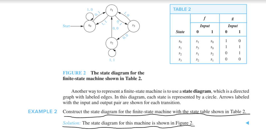
FIGURE 2 The state diagram for the
finite-state machine shown in Table 2.
Another way to represent a finite-state machine is to use a state diagram, which is a directed
graph with labeled edges. In this diagram, each state is represented by a circle. Arrows labeled
with the input and output pair are shown for each transition.
EXAMPLE 2
Construct the state diagram for the finite-state machine with the state table shown in
able 2.
Solution: The state diagram for this machine is shown in Figure 2.
Expert Solution
This question has been solved!
Explore an expertly crafted, step-by-step solution for a thorough understanding of key concepts.

This is a popular solution!

Trending now
This is a popular solution!

Step by step
Solved in 3 steps with 3 images

Knowledge Booster


Learn more about
Need a deep-dive on the concept behind this application? Look no further. Learn more about this topic, electrical-engineering and related others by exploring similar questions and additional content below.Recommended textbooks for you
Introductory Circuit Analysis (13th Edition)
Electrical Engineering
ISBN:
9780133923605
Author:
Robert L. Boylestad
Publisher:
PEARSON

Delmar's Standard Textbook Of Electricity
Electrical Engineering
ISBN:
9781337900348
Author:
Stephen L. Herman
Publisher:
Cengage Learning

Programmable Logic Controllers
Electrical Engineering
ISBN:
9780073373843
Author:
Frank D. Petruzella
Publisher:
McGraw-Hill Education
Introductory Circuit Analysis (13th Edition)
Electrical Engineering
ISBN:
9780133923605
Author:
Robert L. Boylestad
Publisher:
PEARSON
Delmar's Standard Textbook Of Electricity
Electrical Engineering
ISBN:
9781337900348
Author:
Stephen L. Herman
Publisher:
Cengage Learning
Programmable Logic Controllers
Electrical Engineering
ISBN:
9780073373843
Author:
Frank D. Petruzella
Publisher:
McGraw-Hill Education

Fundamentals of Electric Circuits
Electrical Engineering
ISBN:
9780078028229
Author:
Charles K Alexander, Matthew Sadiku
Publisher:
McGraw-Hill Education

Electric Circuits. (11th Edition)
Electrical Engineering
ISBN:
9780134746968
Author:
James W. Nilsson, Susan Riedel
Publisher:
PEARSON

Engineering Electromagnetics
Electrical Engineering
ISBN:
9780078028151
Author:
Hayt, William H. (william Hart), Jr, BUCK, John A.
Publisher:
Mcgraw-hill Education,