Current Attempt in Progress In the circuit of the figure 8 = 3.93 kV, C = 8.70 μF, R₁ = R₂ = R3 = 0.800 MQ. With C completely uncharged, switch S is suddenly closed (at t = 0). At t = 0, what are (a) current i₁ in resistor 1, (b) current i2 in resistor 2, and (c) current i3 in resistor 3? At t = ∞ (that is, after many time constants), what are (d)i₁, (e)i2, and (f)i3? What is the potential difference V₂ across resistor 2 at (g)t = 0 and (h)t = ∞? (a) Number i (b) Number i (c) Number i (d) Number i (e) Number i (f) Number (g) Number i (h) Number i Units Units Units Units Units Units Units Units R₁₂ R₂
Current Attempt in Progress In the circuit of the figure 8 = 3.93 kV, C = 8.70 μF, R₁ = R₂ = R3 = 0.800 MQ. With C completely uncharged, switch S is suddenly closed (at t = 0). At t = 0, what are (a) current i₁ in resistor 1, (b) current i2 in resistor 2, and (c) current i3 in resistor 3? At t = ∞ (that is, after many time constants), what are (d)i₁, (e)i2, and (f)i3? What is the potential difference V₂ across resistor 2 at (g)t = 0 and (h)t = ∞? (a) Number i (b) Number i (c) Number i (d) Number i (e) Number i (f) Number (g) Number i (h) Number i Units Units Units Units Units Units Units Units R₁₂ R₂

Chapter14: Inductance
Section: Chapter Questions
Problem 53P: For the circuit shown below, =20V , L = 4.0 mH, and R = 5.0 . After steady state is reached with S1...

Related questions
Question
Transcribed Image Text:TICHT ORCIC
Current Attempt in Progress
=
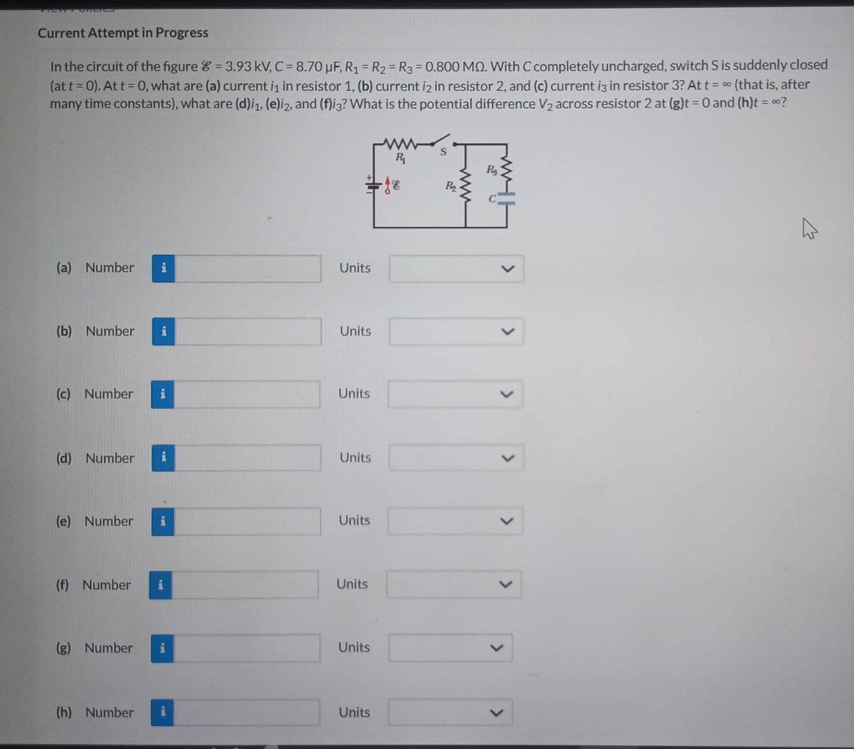
In the circuit of the figure = 3.93 kV, C = 8.70 μF, R₁ = R₂ R3 = 0.800 MQ. With C completely uncharged, switch S is suddenly closed
(at t = 0). At t = 0, what are (a) current i₁ in resistor 1, (b) current i2 in resistor 2, and (c) current i3 in resistor 3? At t = ~ (that is, after
many time constants), what are (d)i₁, (e)i2, and (f)i3? What is the potential difference V₂ across resistor 2 at (g)t = 0 and (h)t = ∞?
(a) Number
(b) Number
(c) Number
(d) Number
(e) Number
(f) Number
(g) Number
(h) Number
I
i
P
i
Units
Units
Units
Units
Units
Units
Units
Units
R₁
-18
fe
S
R₂
<
E
Expert Solution
This question has been solved!
Explore an expertly crafted, step-by-step solution for a thorough understanding of key concepts.

Step by step
Solved in 4 steps

Knowledge Booster


Learn more about
Need a deep-dive on the concept behind this application? Look no further. Learn more about this topic, physics and related others by exploring similar questions and additional content below.Recommended textbooks for you