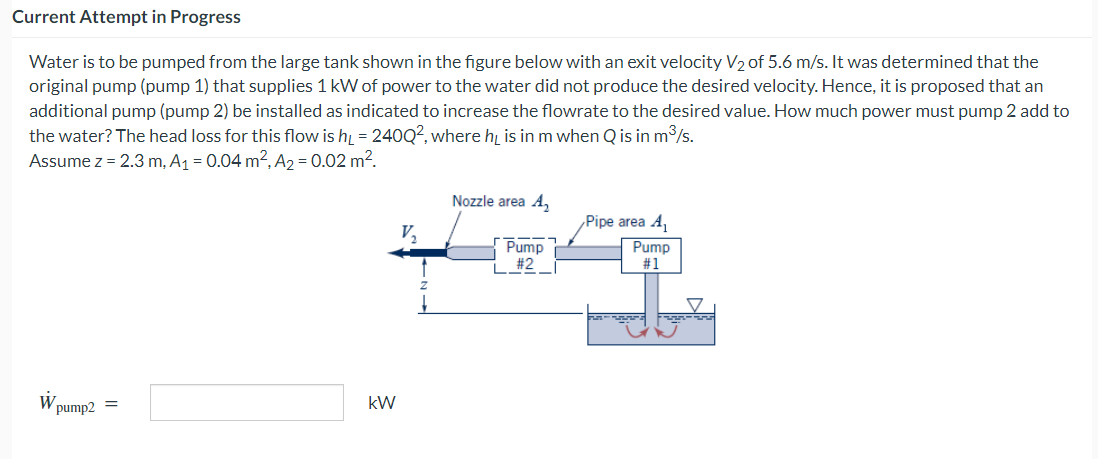
Current Attempt in Progress Water is to be pumped from the large tank shown in the figure below with an exit velocity V₂ of 5.6 m/s. It was determined that the original pump (pump 1) that supplies 1 kW of power to the water did not produce the desired velocity. Hence, it is proposed that an additional pump (pump 2) be installed as indicated to increase the flowrate to the desired value. How much power must pump 2 add to the water? The head loss for this flow is h₁ = 240Q², where h₁ is in m when Q is in m³/s. Assume z = 2.3 m, A₁ = 0.04 m², A₂ = 0.02 m². W. pump2 = Nozzle area 4₂ Pump for #2 kW Pipe area A₁ Pump #1
Current Attempt in Progress Water is to be pumped from the large tank shown in the figure below with an exit velocity V₂ of 5.6 m/s. It was determined that the original pump (pump 1) that supplies 1 kW of power to the water did not produce the desired velocity. Hence, it is proposed that an additional pump (pump 2) be installed as indicated to increase the flowrate to the desired value. How much power must pump 2 add to the water? The head loss for this flow is h₁ = 240Q², where h₁ is in m when Q is in m³/s. Assume z = 2.3 m, A₁ = 0.04 m², A₂ = 0.02 m². W. pump2 = Nozzle area 4₂ Pump for #2 kW Pipe area A₁ Pump #1

Sustainable Energy
2nd Edition
ISBN:9781337551663
Author:DUNLAP, Richard A.
Publisher:DUNLAP, Richard A.
Chapter14: Ocean Thermal Energy Conversion And Ocean Salinity Gradient Energy
Section: Chapter Questions
Problem 14P

Related questions

Question
q10
Transcribed Image Text:Current Attempt in Progress
Water is to be pumped from the large tank shown in the figure below with an exit velocity V₂ of 5.6 m/s. It was determined that the
original pump (pump 1) that supplies 1 kW of power to the water did not produce the desired velocity. Hence, it is proposed that an
additional pump (pump 2) be installed as indicated to increase the flowrate to the desired value. How much power must pump 2 add to
the water? The head loss for this flow is h = 240Q2, where he is in m when Q is in m³/s.
Assume z = 2.3 m, A₁ = 0.04 m², A₂ = 0.02 m².
W
pump2 =
kW
V₂
Nozzle area A₂
Pump
#2
Pipe area A₁
Pump
#1
-
Expert Solution
This question has been solved!
Explore an expertly crafted, step-by-step solution for a thorough understanding of key concepts.

Step by step
Solved in 3 steps with 3 images

Knowledge Booster


Learn more about
Need a deep-dive on the concept behind this application? Look no further. Learn more about this topic, civil-engineering and related others by exploring similar questions and additional content below.Recommended textbooks for you