d) Determine the phasors V₁, VR and Vc. e) Sketch the phasor diagram showing VS, VR, VR, Vc and I. Ī= 1002-20° mA V = 120230° V f = 60 Hz L VL Figure 1. C 35μF Vc VR R
d) Determine the phasors V₁, VR and Vc. e) Sketch the phasor diagram showing VS, VR, VR, Vc and I. Ī= 1002-20° mA V = 120230° V f = 60 Hz L VL Figure 1. C 35μF Vc VR R

Power System Analysis and Design (MindTap Course List)
6th Edition
ISBN:9781305632134
Author:J. Duncan Glover, Thomas Overbye, Mulukutla S. Sarma
Publisher:J. Duncan Glover, Thomas Overbye, Mulukutla S. Sarma
Chapter2: Fundamentals
Section: Chapter Questions
Problem 2.1MCQ: The rms value of v(t)=Vmaxcos(t+) is given by a. Vmax b. Vmax/2 c. 2Vmax d. 2Vmax

Related questions
Question
d) Determine the phasors ?L ,Vr and ?c
e) Sketch the phasor diagram showing ?s, ?r,
?r, ?c and ?
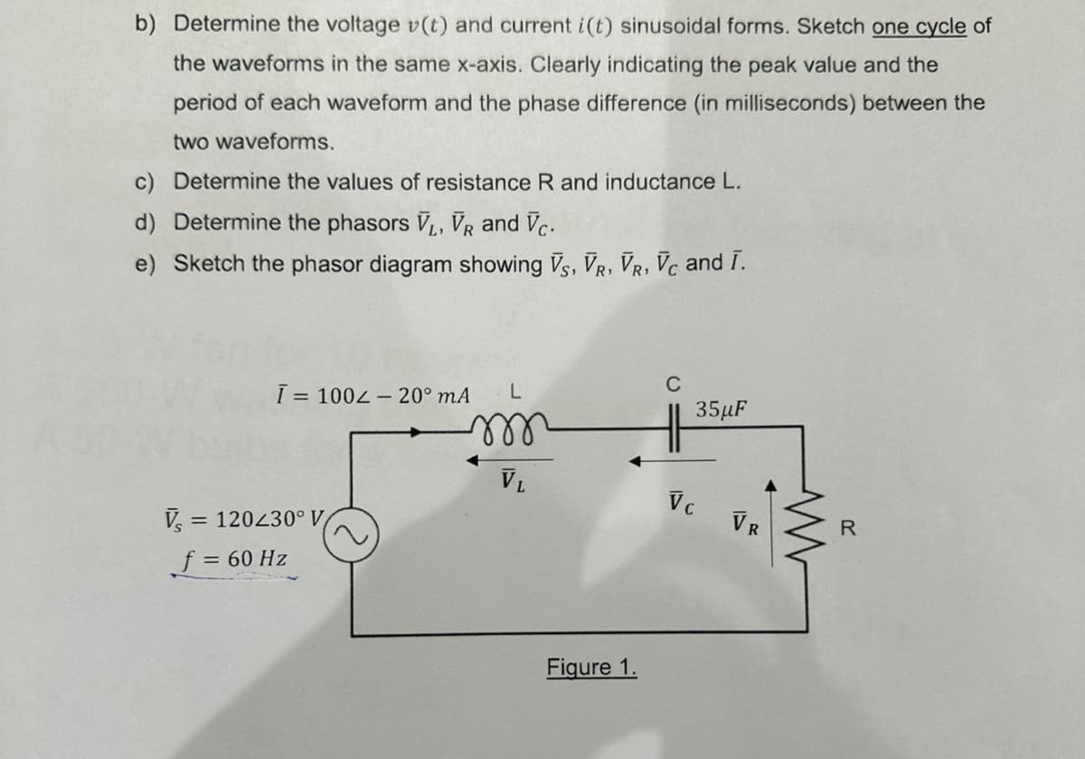
Transcribed Image Text:b) Determine the voltage v(t) and current i(t) sinusoidal forms. Sketch one cycle of
the waveforms in the same x-axis. Clearly indicating the peak value and the
period of each waveform and the phase difference (in milliseconds) between the
two waveforms.
c) Determine the values of resistance R and inductance L.
d) Determine the phasors V₁, VR and Vc.
e) Sketch the phasor diagram showing VS, VR, VR, Vc and I.
L
m
Ī= 100-20⁰ mA
V₁ = = 120230° V
f = 60 Hz
VL
Figure 1.
C
35μF
Vc
VR
www
R
Expert Solution
This question has been solved!
Explore an expertly crafted, step-by-step solution for a thorough understanding of key concepts.

Step by step
Solved in 7 steps with 7 images

Follow-up Questions
Read through expert solutions to related follow-up questions below.
Follow-up Question
Determine the values of resistance R and inductance L

Transcribed Image Text:I= 1002-20° mA
V = 120230° V
f = 60 Hz
୧୪୪୪
VL
End
Figure 1.
35μF
HH
Vc
VR
W
R
Solution
Knowledge Booster


Learn more about
Need a deep-dive on the concept behind this application? Look no further. Learn more about this topic, electrical-engineering and related others by exploring similar questions and additional content below.Recommended textbooks for you
Power System Analysis and Design (MindTap Course …
Electrical Engineering
ISBN:
9781305632134
Author:
J. Duncan Glover, Thomas Overbye, Mulukutla S. Sarma
Publisher:
Cengage Learning
Power System Analysis and Design (MindTap Course …
Electrical Engineering
ISBN:
9781305632134
Author:
J. Duncan Glover, Thomas Overbye, Mulukutla S. Sarma
Publisher:
Cengage Learning