17: There are two questions, first about an ideal diode and then about a modeled diode. For the modeled diode, the voltage across its terminals is 0.7V when it is "on". mich of the following statements are true about the ideal diode above? a. If v = 0, then the diode might be replaced by a short circuit or an open circuit. b. It is possible for i to be positive. c. If v<0, then the diode can be replaced by a dependent current source. d. It is possible for v to be equal to 0. e. If i = 0, then the diode can be replaced by a open circuit. f. If i = 0, then the sign of v (+,-, or 0) cannot be determined. g. None of these statements is true.
17: There are two questions, first about an ideal diode and then about a modeled diode. For the modeled diode, the voltage across its terminals is 0.7V when it is "on". mich of the following statements are true about the ideal diode above? a. If v = 0, then the diode might be replaced by a short circuit or an open circuit. b. It is possible for i to be positive. c. If v<0, then the diode can be replaced by a dependent current source. d. It is possible for v to be equal to 0. e. If i = 0, then the diode can be replaced by a open circuit. f. If i = 0, then the sign of v (+,-, or 0) cannot be determined. g. None of these statements is true.

Power System Analysis and Design (MindTap Course List)
6th Edition
ISBN:9781305632134
Author:J. Duncan Glover, Thomas Overbye, Mulukutla S. Sarma
Publisher:J. Duncan Glover, Thomas Overbye, Mulukutla S. Sarma
Chapter4: Transmission Line Parameters
Section: Chapter Questions
Problem 4.2P: The temperature dependence of resistance is also quantified by the relation R2=R1[ 1+(T2T1) ] where...

Related questions
Question
Transcribed Image Text:Answer:
| C +
There are two questions,
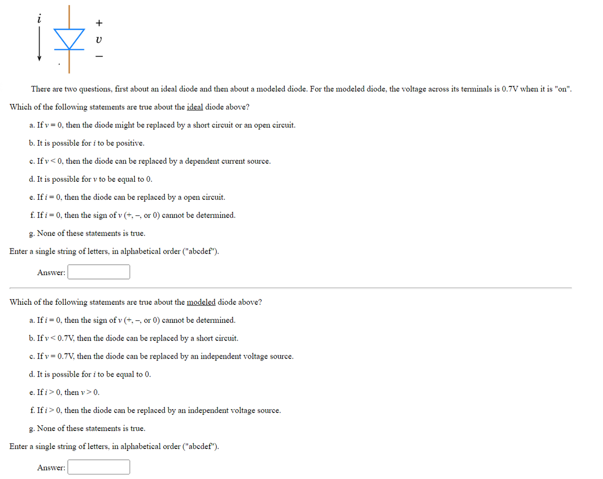
first about an ideal diode and then about a modeled diode. For the modeled diode, the voltage across its terminals is 0.7V when it is "on".
Which of the following statements are true about the ideal diode above?
a. If v = 0, then the diode might be replaced by a short circuit or an open circuit.
b. It is possible for i to be positive.
c. If v<0, then the diode can be replaced by a dependent current source.
d. It is possible for v to be equal to 0.
e. If i = 0, then the diode can be replaced by a open circuit.
f. If i = 0, then the sign of v (+,-, or 0) cannot be determined.
g. None of these statements is true.
Enter a single string of letters, in alphabetical order ("abcdef").
V
Answer:
Which of the following statements are true about the modeled diode above?
a. If i = 0, then the sign of v (+,-, or 0) cannot be determined.
b. If v<0.7V, then the diode can be replaced by a short circuit.
c. If v = 0.7V, then the diode can be replaced by an independent voltage source.
d. It is possible for i to be equal to 0.
e. If i > 0, then v > 0.
f. If i> 0, then the diode can be replaced by an independent voltage source.
g. None of these statements is true.
Enter a single string of letters, in alphabetical order ("abcdef").
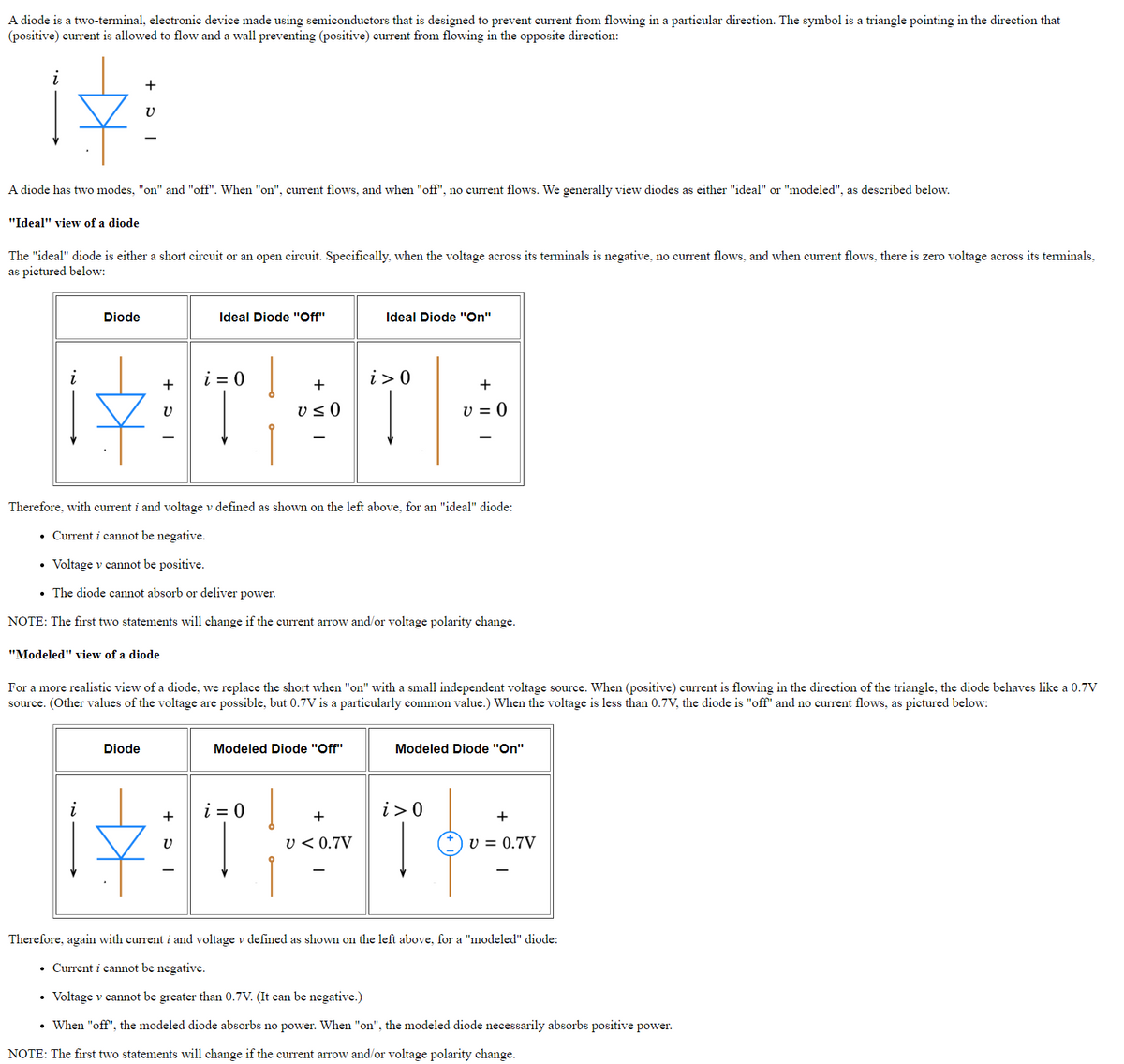
Transcribed Image Text:A diode is a two-terminal, electronic device made using semiconductors that is designed to prevent current from flowing in a particular direction. The symbol is a triangle pointing in the direction that
(positive) current is allowed to flow and a wall preventing (positive) current from flowing in the opposite direction:
+
17:
A diode has two modes, "on" and "off". When "on", current flows, and when "off", no current flows. We generally view diodes as either "ideal" or "modeled", as described below.
"Ideal" view of a diode
The "ideal" diode is either a short circuit or an open circuit. Specifically, when the voltage across its terminals is negative, no current flows, and when current flows, there is zero voltage across its terminals,
as pictured below:
Diode
Ideal Diode "Off"
i=0
+
&:T
V
+
U≤0
Diode
Ideal Diode "On"
Therefore, with current i and voltage v defined as shown on the left above, for an "ideal" diode:
• Current i cannot be negative.
• Voltage v cannot be positive.
. The diode cannot absorb or deliver power.
NOTE: The first two statements will change if the current arrow and/or voltage polarity change.
"Modeled" view of a diode
Modeled Diode "Off"
i> 0
For a more realistic view of a diode, we replace the short when "on" with a small independent voltage source. When (positive) current is flowing in the direction of the triangle, the diode behaves like a 0.7V
source. (Other values of the voltage are possible, but 0.7V is a particularly common value.) When the voltage is less than 0.7V, the diode is "off" and no current flows, as pictured below:
+
+
V = 0
i> 0
i=0 |
+
1&3TH T
V
V < 0.7V
Modeled Diode "On"
V = 0.7V
Therefore, again with current i and voltage v defined as shown on the left above, for a "modeled" diode:
• Current i cannot be negative.
• Voltage v cannot be greater than 0.7V. (It can be negative.)
• When "off", the modeled diode absorbs no power. When "on", the modeled diode necessarily absorbs positive power.
NOTE: The first two statements will change if the current arrow and/or voltage polarity change.
Expert Solution
This question has been solved!
Explore an expertly crafted, step-by-step solution for a thorough understanding of key concepts.

This is a popular solution!

Trending now
This is a popular solution!

Step by step
Solved in 3 steps with 2 images

Knowledge Booster


Learn more about
Need a deep-dive on the concept behind this application? Look no further. Learn more about this topic, electrical-engineering and related others by exploring similar questions and additional content below.Recommended textbooks for you
Power System Analysis and Design (MindTap Course …
Electrical Engineering
ISBN:
9781305632134
Author:
J. Duncan Glover, Thomas Overbye, Mulukutla S. Sarma
Publisher:
Cengage Learning
Power System Analysis and Design (MindTap Course …
Electrical Engineering
ISBN:
9781305632134
Author:
J. Duncan Glover, Thomas Overbye, Mulukutla S. Sarma
Publisher:
Cengage Learning