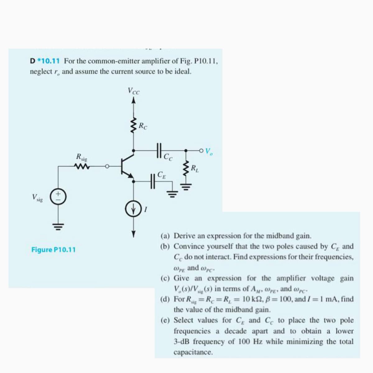
D*10.11 For the common-emitter amplifier of Fig. P10.11, neglect r, and assume the current source to be ideal. Vcc Rc Ras RL CE Vsig (a) Derive an expression for the midband gain. (b) Convince yourself that the two poles caused by C and Co do not interact. Find expressions for their frequencies, Figure P10.11 @PE and Wpc: gain (c) Give an expression for the amplifier volta V,(s)/V(s) in terms of Ay, @PE and @pc:

Introductory Circuit Analysis (13th Edition)
13th Edition
ISBN:9780133923605
Author:Robert L. Boylestad
Publisher:Robert L. Boylestad
Chapter1: Introduction
Section: Chapter Questions
Problem 1P: Visit your local library (at school or home) and describe the extent to which it provides literature...
icon
Related questions
icon
Concept explainers
Question
D *10.11 For the common-emitter amplifier of Fig. P10.11,
neglect r, and assume the current source to be ideal.
Vcc
Rc
Vo
Rig
RL
(a) Derive an expression for the midband gain.
(b) Convince yourself that the two poles caused by C and
Co do not interact. Find expressions for their frequencies,
@pg and wpc.
(c) Give an expression for the amplifier voltage gain
V,(s)/V(s) in terms of Ay, @PE
(d) For R R=R, 10 k2, B= 100, and I 1 mA, find
the value of the midband gain.
(e) Select values for C and C to place the two pole
frequencies a decade apart and to obtain a lower
3-dB frequency of 100 Hz while minimizing the total
capacitance.
Figure P10.11
and wrc
%3D
%3D
Transcribed Image Text:D *10.11 For the common-emitter amplifier of Fig. P10.11, neglect r, and assume the current source to be ideal. Vcc Rc Vo Rig RL (a) Derive an expression for the midband gain. (b) Convince yourself that the two poles caused by C and Co do not interact. Find expressions for their frequencies, @pg and wpc. (c) Give an expression for the amplifier voltage gain V,(s)/V(s) in terms of Ay, @PE (d) For R R=R, 10 k2, B= 100, and I 1 mA, find the value of the midband gain. (e) Select values for C and C to place the two pole frequencies a decade apart and to obtain a lower 3-dB frequency of 100 Hz while minimizing the total capacitance. Figure P10.11 and wrc %3D %3D
Expert Solution
trending now

Trending now

This is a popular solution!

steps

Step by step

Solved in 2 steps with 2 images

Blurred answer
Knowledge Booster
Power amplifier
Learn more about
Need a deep-dive on the concept behind this application? Look no further. Learn more about this topic, electrical-engineering and related others by exploring similar questions and additional content below.
Similar questions
  • SEE MORE QUESTIONS
Recommended textbooks for you
Introductory Circuit Analysis (13th Edition)
Electrical Engineering
ISBN:
9780133923605
Author:
Robert L. Boylestad
Publisher:
PEARSON
Delmar's Standard Textbook Of Electricity
Electrical Engineering
ISBN:
9781337900348
Author:
Stephen L. Herman
Publisher:
Cengage Learning
Programmable Logic Controllers
Electrical Engineering
ISBN:
9780073373843
Author:
Frank D. Petruzella
Publisher:
McGraw-Hill Education
Fundamentals of Electric Circuits
Electrical Engineering
ISBN:
9780078028229
Author:
Charles K Alexander, Matthew Sadiku
Publisher:
McGraw-Hill Education
Electric Circuits. (11th Edition)
Electrical Engineering
ISBN:
9780134746968
Author:
James W. Nilsson, Susan Riedel
Publisher:
PEARSON
Engineering Electromagnetics
Electrical Engineering
ISBN:
9780078028151
Author:
Hayt, William H. (william Hart), Jr, BUCK, John A.
Publisher:
Mcgraw-hill Education,