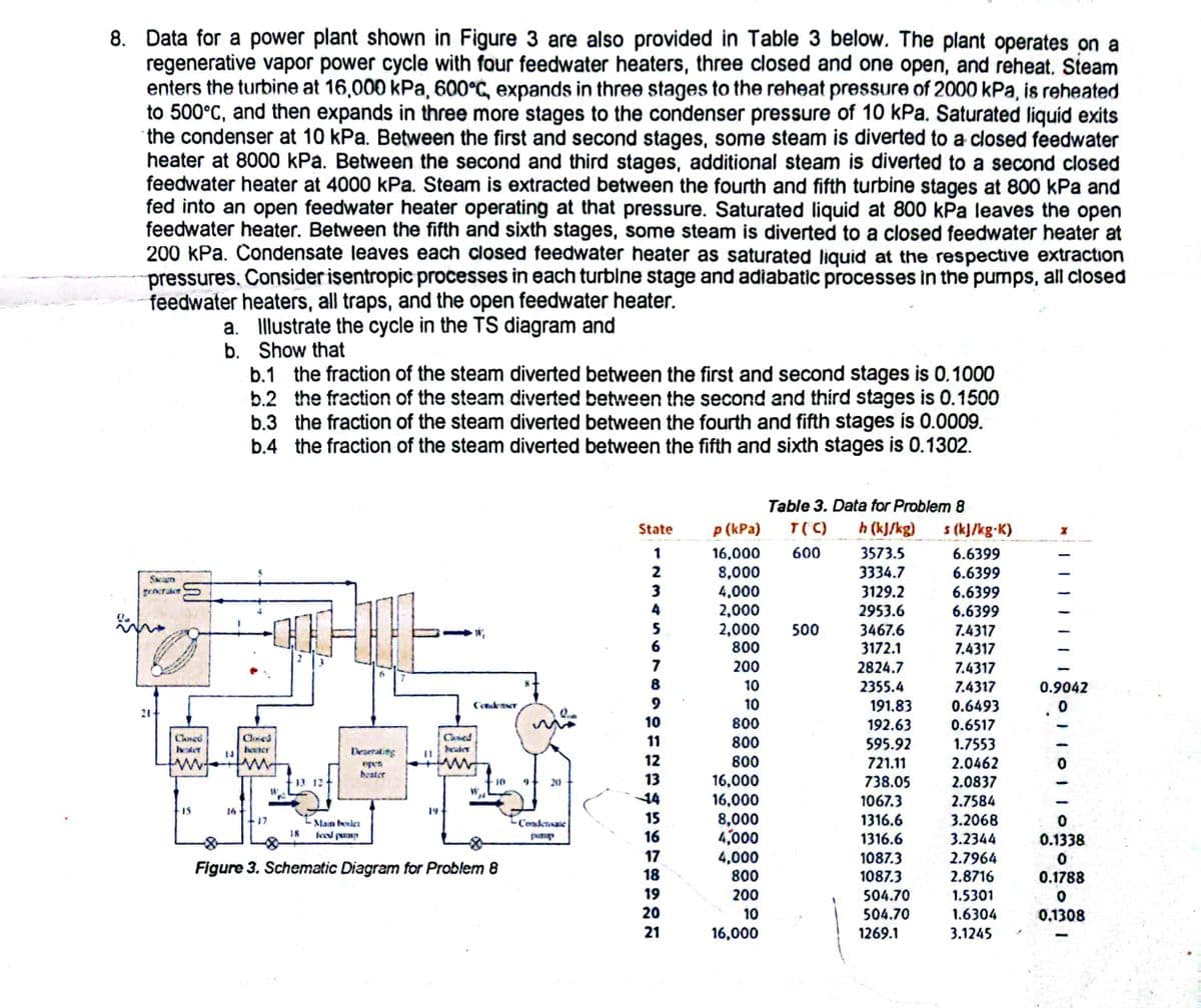
Data for a power plant shown in Figure 3 are also provided in Table 3 below. The plant operates on a regenerative vapor power cycle with four feedwater heaters, three closed and one open, and reheat. Steam enters the turbine at 16,000 kPa, 600°C, expands in three stages to the reheat pressure of 2000 kPa, is reheated to 500°C, and then expands in three more stages to the condenser pressure of 10 kPa. Saturated liquid exits the condenser at 10 kPa. Between the first and second stages, some steam is diverted to a closed feedwater heater at 8000 kPa. Between the second and third stages, additional steam is diverted to a second closed feedwater heater at 4000 kPa. Steam is extracted between the fourth and fifth turbine stages at 800 kPa and fed into an open feedwater heater operating at that pressure. Saturated liquid at 800 kPa leaves the open feedwater heater. Between the fifth and sixth stages, some steam is diverted to a closed feedwater heater at 200 kPa. Condensate leaves each closed feedwater heater as saturated liquid at the respective extraction pressures. Consider isentropic processes in each turbine stage and adiabatic processes in the pumps, all closed feedwater heaters, all traps, and the open feedwater heater. a. Illustrate the cycle in the TS diagram and
Data for a power plant shown in Figure 3 are also provided in Table 3 below. The plant operates on a regenerative vapor power cycle with four feedwater heaters, three closed and one open, and reheat. Steam enters the turbine at 16,000 kPa, 600°C, expands in three stages to the reheat pressure of 2000 kPa, is reheated to 500°C, and then expands in three more stages to the condenser pressure of 10 kPa. Saturated liquid exits the condenser at 10 kPa. Between the first and second stages, some steam is diverted to a closed feedwater heater at 8000 kPa. Between the second and third stages, additional steam is diverted to a second closed feedwater heater at 4000 kPa. Steam is extracted between the fourth and fifth turbine stages at 800 kPa and fed into an open feedwater heater operating at that pressure. Saturated liquid at 800 kPa leaves the open feedwater heater. Between the fifth and sixth stages, some steam is diverted to a closed feedwater heater at 200 kPa. Condensate leaves each closed feedwater heater as saturated liquid at the respective extraction pressures. Consider isentropic processes in each turbine stage and adiabatic processes in the pumps, all closed feedwater heaters, all traps, and the open feedwater heater. a. Illustrate the cycle in the TS diagram and

Elements Of Electromagnetics
7th Edition
ISBN:9780190698614
Author:Sadiku, Matthew N. O.
Publisher:Sadiku, Matthew N. O.
ChapterMA: Math Assessment
Section: Chapter Questions
Problem 1.1MA

Related questions
Question
Please give only the ts diagram
Transcribed Image Text:8. Data for a power plant shown in Figure 3 are also provided in Table 3 below. The plant operates on a
regenerative vapor power cycle with four feedwater heaters, three closed and one open, and reheat. Steam
enters the turbine at 16,000 kPa, 600°C, expands in three stages to the reheat pressure of 2000 kPa, is reheated
to 500°C, and then expands in three more stages to the condenser pressure of 10 kPa. Saturated liquid exits
the condenser at 10 kPa. Between the first and second stages, some steam is diverted to a closed feedwater
heater at 8000 kPa. Between the second and third stages, additional steam is diverted to a second closed
feedwater heater at 4000 kPa. Steam is extracted between the fourth and fifth turbine stages at 800 kPa and
fed into an open feedwater heater operating at that pressure. Saturated liquid at 800 kPa leaves the open
feedwater heater. Between the fifth and sixth stages, some steam is diverted to a closed feedwater heater at
200 kPa. Condensate leaves each closed feedwater heater as saturated liquid at the respective extraction
pressures. Consider isentropic processes in each turbine stage and adiabatic processes in the pumps, all closed
feedwater heaters, all traps, and the open feedwater heater.
a. Illustrate the cycle in the TS diagram and
b.
Show that
Seam
generaler
21-
Closed
15
16
L"
b.1 the fraction of the steam diverted between the first and second stages is 0.1000
b.2 the fraction of the steam diverted between the second and third stages is 0.1500
the fraction of the steam diverted between the fourth and fifth stages is 0.0009.
the fraction of the steam diverted between the fifth and sixth stages is 0.1302.
b.3
b.4
Cloned
bouter
17
18
Deserating
open
beater
Main boric
feed pump
19
Caned
W₁
Condenser
10
Figure 3. Schematic Diagram for Problem 8
8
20
-Condensate
party
State
1234567
8
9
10
11
12
13
14
15
16
17
18
19
20
21
Table 3. Data for Problem 8
p (kPa) T(C) h (kJ/kg) s (kJ/kg-K)
16,000 600
8,000
4,000
2,000
2,000 500
800
200
10
10
800
800
800
16,000
16,000
8,000
4,000
4,000
800
200
10
16,000
3573.5
3334.7
3129.2
2953.6
3467.6
3172.1
2824.7
2355.4
191.83
192.63
595.92
721.11
738.05
1067.3
1316.6
1316.6
1087.3
1087.3
504.70
504.70
1269.1
6.6399
6.6399
6.6399
6.6399
7.4317
7.4317
7.4317
7.4317
0.6493
0.6517
1.7553
2.0462
2.0837
2.7584
3.2068
3.2344
2.7964
2.8716
1.5301
1.6304
3.1245
0.9042
.0
0
0.1338
0
0.1788
0
0.1308
Expert Solution
This question has been solved!
Explore an expertly crafted, step-by-step solution for a thorough understanding of key concepts.

This is a popular solution!

Trending now
This is a popular solution!

Step by step
Solved in 3 steps with 2 images

Knowledge Booster


Learn more about
Need a deep-dive on the concept behind this application? Look no further. Learn more about this topic, mechanical-engineering and related others by exploring similar questions and additional content below.Recommended textbooks for you
Elements Of Electromagnetics
Mechanical Engineering
ISBN:
9780190698614
Author:
Sadiku, Matthew N. O.
Publisher:
Oxford University Press

Mechanics of Materials (10th Edition)
Mechanical Engineering
ISBN:
9780134319650
Author:
Russell C. Hibbeler
Publisher:
PEARSON

Thermodynamics: An Engineering Approach
Mechanical Engineering
ISBN:
9781259822674
Author:
Yunus A. Cengel Dr., Michael A. Boles
Publisher:
McGraw-Hill Education
Elements Of Electromagnetics
Mechanical Engineering
ISBN:
9780190698614
Author:
Sadiku, Matthew N. O.
Publisher:
Oxford University Press
Mechanics of Materials (10th Edition)
Mechanical Engineering
ISBN:
9780134319650
Author:
Russell C. Hibbeler
Publisher:
PEARSON
Thermodynamics: An Engineering Approach
Mechanical Engineering
ISBN:
9781259822674
Author:
Yunus A. Cengel Dr., Michael A. Boles
Publisher:
McGraw-Hill Education

Control Systems Engineering
Mechanical Engineering
ISBN:
9781118170519
Author:
Norman S. Nise
Publisher:
WILEY

Mechanics of Materials (MindTap Course List)
Mechanical Engineering
ISBN:
9781337093347
Author:
Barry J. Goodno, James M. Gere
Publisher:
Cengage Learning

Engineering Mechanics: Statics
Mechanical Engineering
ISBN:
9781118807330
Author:
James L. Meriam, L. G. Kraige, J. N. Bolton
Publisher:
WILEY