Design a 17-ft tall rectangular tied column A-B in a braced frame to support an unfactored axial dead load of 550 kip (including self-weight) and an unfactored axial live load of 300 kip (see figure). In addition to the axial loads, the column is also subject to a factored end moment as shown in the figure below. (a) Check whether column AB is a long/slender or short column. [Note: you must use and mark on the alignment chart to show how you determine the effective length factor, k] (b) Determine the minimum number of #10 bar(s) required to carry the factored loads. Select the reinforcing bars to be placed in the two end faces only (see figure below). (c) Neglecting shear, what is the maximum spacing of #3 ties for the column? -24 in- 18.2 in 7= 0.80 22"x24" 22"x30" ? #10 30 ft | 34" 22"x 24"- B A 22"x30" 30 ft 15 ft 17 ft PD = 550 kip PL = 300 kip PD=740 kip PL= 400 kip M₁ = 330 ft-kip 17 ft B f'c = 4 ksi (normal weight) Ec= 3.605 x 10³ ksi (concrete MOE) fy = 60 ksi
Design a 17-ft tall rectangular tied column A-B in a braced frame to support an unfactored axial dead load of 550 kip (including self-weight) and an unfactored axial live load of 300 kip (see figure). In addition to the axial loads, the column is also subject to a factored end moment as shown in the figure below. (a) Check whether column AB is a long/slender or short column. [Note: you must use and mark on the alignment chart to show how you determine the effective length factor, k] (b) Determine the minimum number of #10 bar(s) required to carry the factored loads. Select the reinforcing bars to be placed in the two end faces only (see figure below). (c) Neglecting shear, what is the maximum spacing of #3 ties for the column? -24 in- 18.2 in 7= 0.80 22"x24" 22"x30" ? #10 30 ft | 34" 22"x 24"- B A 22"x30" 30 ft 15 ft 17 ft PD = 550 kip PL = 300 kip PD=740 kip PL= 400 kip M₁ = 330 ft-kip 17 ft B f'c = 4 ksi (normal weight) Ec= 3.605 x 10³ ksi (concrete MOE) fy = 60 ksi

Chapter2: Loads On Structures
Section: Chapter Questions
Problem 1P

Related questions
Question
![Design a 17-ft tall rectangular tied column A-B in a braced frame to support an unfactored
axial dead load of 550 kip (including self-weight) and an unfactored axial live load of 300
kip (see figure). In addition to the axial loads, the column is also subject to a factored end
moment as shown in the figure below.
(a) Check whether column AB is a long/slender or short column. [Note: you must use
and mark on the alignment chart to show how you determine the effective length
factor, k]
(b) Determine the minimum number of #10 bar(s) required to carry the factored loads.
Select the reinforcing bars to be placed in the two end faces only (see figure below).
(c) Neglecting shear, what is the maximum spacing of #3 ties for the column?
-24 in-
18.2 in
Y = 0.80
0
22"x24"
22”x30"
22"x 24"
30 ft
? #10
34"
B
A
0
22"x30
30 ft
15 ft
17 ft
PD = 550 kip
PL = 300 kip
PD=740 kip
PL = 400 kip
M₁ = 330 ft-kip
17 ft
B
A
f'c = 4 ksi (normal weight)
Ec= 3.605 x 10³ ksi (concrete MOE)
fy = 60 ksi](/v2/_next/image?url=https%3A%2F%2Fcontent.bartleby.com%2Fqna-images%2Fquestion%2F260a23ec-c202-4293-b91a-dda22b3dff03%2F75dc0f6d-2674-423a-beaf-e0dddea7bc31%2F8w5ph4l_processed.png&w=3840&q=75)
Transcribed Image Text:Design a 17-ft tall rectangular tied column A-B in a braced frame to support an unfactored
axial dead load of 550 kip (including self-weight) and an unfactored axial live load of 300
kip (see figure). In addition to the axial loads, the column is also subject to a factored end
moment as shown in the figure below.
(a) Check whether column AB is a long/slender or short column. [Note: you must use
and mark on the alignment chart to show how you determine the effective length
factor, k]
(b) Determine the minimum number of #10 bar(s) required to carry the factored loads.
Select the reinforcing bars to be placed in the two end faces only (see figure below).
(c) Neglecting shear, what is the maximum spacing of #3 ties for the column?
-24 in-
18.2 in
Y = 0.80
0
22"x24"
22”x30"
22"x 24"
30 ft
? #10
34"
B
A
0
22"x30
30 ft
15 ft
17 ft
PD = 550 kip
PL = 300 kip
PD=740 kip
PL = 400 kip
M₁ = 330 ft-kip
17 ft
B
A
f'c = 4 ksi (normal weight)
Ec= 3.605 x 10³ ksi (concrete MOE)
fy = 60 ksi
Transcribed Image Text:VA
50.0-
10.0
5.0-
3.0-
2.0-
1.0
0.9
0.8
0.7.
0.5-
0.4-
0.3
0.2
0.1-
U
H
1.0
0.9
0.8
0.7
0.6
0.5
& ~~~IIIןשיידי חווויןיןיויו
Te
ה14
50.0
10.0
5.0
3.0
2.0
1.0
0.9
0.8
0.7
0.6
0.5
04
0.3
0.2
0.1
0
WA
100.0
500
30.0-
20.0
10.0
8.0
7.0
6.0
5.0
4.0
3.0
2.0
1.0
ויח
0
▬▬▬▬▬▬▬▬▬▬▬▬▬▬▬▬▬▬▬|||
ד
T
*
20
י
יויו
20.0
10.0
5.0
4.0
3.0
2.0
15
1.0
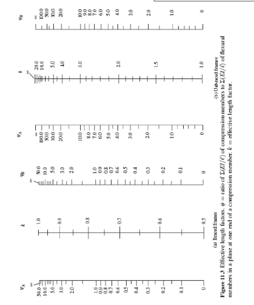
(a) Braced frames
(b) Unbraced frames
Figure 11.3 Effective length factors. = ratio of E(EI/C) of compression members to Σ(EI/) of flexural
members in a plane at one end of a compression member. k= effective length factor.
ווי חוויויויןוןון
WB
100.0
50.0
30.0
20.0
10.0
9.0
8.0
60
5.0
4.0
3.0
2.0
1.0
Expert Solution
This question has been solved!
Explore an expertly crafted, step-by-step solution for a thorough understanding of key concepts.

This is a popular solution!
Step 1: Introducing Given data
VIEWStep 2: Calculation of factors
VIEWStep 3: Calculation of effective length factor (k) from charts
VIEWStep 4: Determine the type of column
VIEWStep 5: Calculation of Kn & Rn
VIEWStep 6: Calculation of Reinforcement ratio
VIEWStep 7: Calculation of Number of #10 bars
VIEWStep 8: Calculate Spacing of ties
VIEWSolution
VIEW
Trending now
This is a popular solution!

Step by step
Solved in 9 steps with 12 images

Knowledge Booster


Learn more about
Need a deep-dive on the concept behind this application? Look no further. Learn more about this topic, civil-engineering and related others by exploring similar questions and additional content below.Recommended textbooks for you

Structural Analysis (10th Edition)
Civil Engineering
ISBN:
9780134610672
Author:
Russell C. Hibbeler
Publisher:
PEARSON

Principles of Foundation Engineering (MindTap Cou…
Civil Engineering
ISBN:
9781337705028
Author:
Braja M. Das, Nagaratnam Sivakugan
Publisher:
Cengage Learning
Structural Analysis (10th Edition)
Civil Engineering
ISBN:
9780134610672
Author:
Russell C. Hibbeler
Publisher:
PEARSON
Principles of Foundation Engineering (MindTap Cou…
Civil Engineering
ISBN:
9781337705028
Author:
Braja M. Das, Nagaratnam Sivakugan
Publisher:
Cengage Learning

Fundamentals of Structural Analysis
Civil Engineering
ISBN:
9780073398006
Author:
Kenneth M. Leet Emeritus, Chia-Ming Uang, Joel Lanning
Publisher:
McGraw-Hill Education


Traffic and Highway Engineering
Civil Engineering
ISBN:
9781305156241
Author:
Garber, Nicholas J.
Publisher:
Cengage Learning