Design the combinatorial circuit that that takes the 4-bit number KLMN as input and performs the following operations to create the 4-bit PRST output. • When the input is between 0-6 then the output is plus .6 of the input When the input is between 7-8 then the output is a "don't care" condition When the input is between 9-F then the output is minus 6 of the input (a) Construct a truth table and optimize the output functions P, R, S and T with K-Maps. (b) Draw the circuit diagram of the output function S with only 2-input NAND gates and inverters. (c) Draw the circuit diagram of the output function T with only 2-input NOR gates and inverters.
Design the combinatorial circuit that that takes the 4-bit number KLMN as input and performs the following operations to create the 4-bit PRST output. • When the input is between 0-6 then the output is plus .6 of the input When the input is between 7-8 then the output is a "don't care" condition When the input is between 9-F then the output is minus 6 of the input (a) Construct a truth table and optimize the output functions P, R, S and T with K-Maps. (b) Draw the circuit diagram of the output function S with only 2-input NAND gates and inverters. (c) Draw the circuit diagram of the output function T with only 2-input NOR gates and inverters.

Power System Analysis and Design (MindTap Course List)
6th Edition
ISBN:9781305632134
Author:J. Duncan Glover, Thomas Overbye, Mulukutla S. Sarma
Publisher:J. Duncan Glover, Thomas Overbye, Mulukutla S. Sarma
Chapter6: Power Flows
Section: Chapter Questions
Problem 6.15P

Related questions

Question
Thanks a lot.
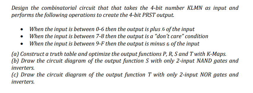
Transcribed Image Text:Design the combinatorial circuit that that takes the 4-bit number KLMN as input and
performs the following operations to create the 4-bit PRST output.
• When the input is between 0-6 then the output is plus.6 of the input
• When the input is between 7-8 then the output is a "don't care" condition
• When the input is between 9-F then the output is minus 6 of the input
(a) Construct a truth table and optimize the output functions P, R, S and T with K-Maps.
(b) Draw the circuit diagram of the output function S with only 2-input NAND gates and
inverters.
(c) Draw the circuit diagram of the output function T with only 2-input NOR gates and
inverters.
Expert Solution
Step 1
(a)
Draw the truth table for the above-given situations.
|
Inputs |
Outputs |
||||||
|
K |
L |
M |
N |
P |
R |
S |
T |
|
0 |
0 |
0 |
0 |
0 |
1 |
1 |
0 |
|
0 |
0 |
0 |
1 |
0 |
1 |
1 |
1 |
|
0 |
0 |
1 |
0 |
1 |
0 |
0 |
0 |
|
0 |
0 |
1 |
1 |
1 |
0 |
0 |
1 |
|
0 |
1 |
0 |
0 |
1 |
0 |
1 |
0 |
|
0 |
1 |
0 |
1 |
1 |
0 |
1 |
1 |
|
0 |
1 |
1 |
0 |
1 |
1 |
0 |
0 |
|
0 |
1 |
1 |
1 |
d |
d |
d |
d |
|
1 |
0 |
0 |
0 |
d |
d |
d |
d |
|
1 |
0 |
0 |
1 |
0 |
1 |
0 |
0 |
|
1 |
0 |
1 |
0 |
0 |
1 |
0 |
1 |
|
1 |
0 |
1 |
1 |
0 |
1 |
1 |
0 |
|
1 |
1 |
0 |
0 |
0 |
1 |
1 |
1 |
|
1 |
1 |
0 |
1 |
1 |
0 |
0 |
0 |
|
1 |
1 |
1 |
0 |
1 |
0 |
0 |
1 |
|
1 |
1 |
1 |
1 |
1 |
0 |
1 |
0 |
Step 2
Draw the K-map for the function P.

Step 3
Draw the K-map for the function R.

Step 4
Draw the K-map for the function S.


Step by step
Solved in 8 steps with 6 images

Knowledge Booster


Learn more about
Need a deep-dive on the concept behind this application? Look no further. Learn more about this topic, electrical-engineering and related others by exploring similar questions and additional content below.Recommended textbooks for you
Power System Analysis and Design (MindTap Course …
Electrical Engineering
ISBN:
9781305632134
Author:
J. Duncan Glover, Thomas Overbye, Mulukutla S. Sarma
Publisher:
Cengage Learning
Power System Analysis and Design (MindTap Course …
Electrical Engineering
ISBN:
9781305632134
Author:
J. Duncan Glover, Thomas Overbye, Mulukutla S. Sarma
Publisher:
Cengage Learning