
Electric Motor Control
10th Edition
ISBN: 9781133702818
Author: Herman
Publisher: CENGAGE L
expand_more
expand_more
format_list_bulleted
Related questions
Question
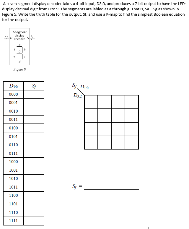

Transcribed Image Text:A seven segment display decoder takes a 4-bit input, D3:0, and produces a 7-bit output to have the LEDS
display decimal digit from 0 to 9. The segments are labled as a through g. That is, Sa - Sg as shown in
Figure 5. Write the truth table for the output, Sf, and use a K-map to find the simplest Boolean equation
for the output.
7-segment
display
0 decoder Ss4
a
e
Figure 5
D3.0
Sf
Sf. D10
0000
D32
0001
0010
0011
0100
0101
0110
0111
1000
1001
1010
1011
Sp =
1100
1101
1110
1111
Expert Solution
This question has been solved!
Explore an expertly crafted, step-by-step solution for a thorough understanding of key concepts.

This is a popular solution

Trending nowThis is a popular solution!

Step by stepSolved in 3 steps with 3 images

Knowledge Booster


Learn more about
Need a deep-dive on the concept behind this application? Look no further. Learn more about this topic, electrical-engineering and related others by exploring similar questions and additional content below.Similar questions
- 1. Gray code to Binary converter: Gray code is one of the codes used in digital systems. It has the advantage over binary numbers that only one bit in the code word changes when going from one number to the next. (See Table 1). Design a combinational circuit with 4 inputs and 4 outputs that converts a four- bit gray code number into an equivalent four-bit Binary number. Use Karnaugh map technique for simplification. Use LogicWorks for pre-lab demonstrations. Select the library "7400dev.clf* in the Parts Palette and then select the XOR chip 74-86. This would give you a set of 4 XOR's as shown in Fig. 1, just like the hardware chip 74-86. You could use as many as needed from these XOR gates in your design. Get back to ALL LIBRARIES and select switches for the inputs and Binary Probes as indicators of the outputs. Verify your design in the pre-Lab. During the Lab construct the circuit and verify its operations.arrow_forwardThe numbers from 0-9 and a no characters is the Basic 1 digit seven segment display * .can show False True In a (CA) method of 7 segments, the anodes of all the LED segments are * "connected to the logic "O False True Some times may run out of pins on your Arduino board and need to not extend it * .with shift registers True Falsearrow_forwardConstruct the logic for 4-bit binary adder-subtractor using 4-bit parallel adder and XOR gates, draw the logic diagram, construct the circuit on hardware and complete the truth tablearrow_forward
- H.W: Reduce the combinational logic circuit in Figure below to a minimum form.arrow_forwardparity generator design, construct and test a circuit that generates an even parity bit ffrom four messages bits . use XOR gates. adding one more XOR gate, expand the circuit so that it generates an odd parity bit also.arrow_forwardFor the input waveforms in Figure , what logic circuit will generate the output waveform shown? Explain in detail for each. Inputs B Output X Inputs B Output Xarrow_forward
- New Solutionarrow_forward9 Part 1 of 2 Mc Graw Hill Required information Consider the logic gate circuit shown in the given figure. A (S1)-0- B (S2)-0 C (S3)-0- AB B BC B+C What is the Boolean equation for the given figure? ***************** The Boolean equation for the given figure is (Click to select) Note: This is a multi-part question. Once an answer is submitted, you will be unable to return to this part.arrow_forwardBuild a truth table and draw the output wave form for the following logic gates shown in Figure Q2. A o B Co Do E o D D Figure Q2 Zarrow_forward
- Nonearrow_forward| Solve all parts. Will give thumb's up| If you can't do all please don't attempt the questions.arrow_forwardGrey converters are often used in industrial circuits where the normal sequence of binary numbers may produce ambiguity during transition. This is elliminated with the Grey code, as only one bit changes, during a normal transition of sequential numbers. Show the logic required to convert a 10-bit binary number to Gray code and use that logic to convert the following to Gray code: a) 1010101010 b) 1111100000 c) 0000001110 d) 1111111111arrow_forward
arrow_back_ios
SEE MORE QUESTIONS
arrow_forward_ios
Recommended textbooks for you