Design the sequential circuit based on the state transition diagram and state table shown below.
Q: The characteristic equation of a closed loop transfer function is given by s²+(4+k) s +5+ka=0, where…
A:
Q: Required information A parallel resonance circuit has a resistance of 2 kQ and half-power…
A:
Q: Figure P6.1-1 shows Fourier spectra of signals gi(t) and g2 (1). Determine the Nyquist interval and…
A:
Q: For the following mechanical system, find the transfer function G(s) = X1(s)/F(s), without using…
A:
Q: A 60-Hz three-phase transmission line is 180 mi long. It has a total series impedance of 40 + j150 2…
A: The problem is based on the analysis of different models of transmission lines. Short-line…
Q: 5. Draw the digital circuit to verify De-Morgan's theorems for three variables. You can draw the…
A:
Q: * Calculate the quivalent industance. L tomo L = 5 Harry Leg. fam mo
A: It is given that L=5 Henry
Q: Vin R₁ -444 12 a R₂ } ✓ A) Sketch and dimension the magnitude of the gain | Vout/Vin | vs. frequency…
A:
Q: An application of Kirchhoff's Rules to the circuit shown results in the following system of…
A: The answer is option A.
Q: A Moore sequential circuit has three inputs (X2, X₁, and Xo) that specify a temperature range in a…
A:
Q: 15.10 Design an op amp-based high-pass filter with a cut- off frequency of 4 kHz and a passband gain…
A:
Q: 3. The electric field of a plane wave is given by E = â 3 cos(@t-kz+75) xe-² V/m and the…
A: Answer : given that the electric field of the plane wave is given by E→ =a^x 3cosωt-kz+75°×e-αz V/m…
Q: vt CALCULATE V. FOR THE CIRCUIT BELOW AND SKETCH THE OUTPUTT HAUFFORM t t Vin D DH 22.0kn SV V6
A:
Q: Solve the equation for the transfer function H(s) using the Laplace transform and evaluate its zeros…
A: The given circuit is shown below, We need to derive the equation for the transfer function Hs using…
Q: A hard-drawn copper conductor has a diameter of 0.41 in. What is the cross sectional area of this…
A: In this question We need to determine the cross sectional area of this conductor in cmil. We know…
Q: Calculate the power delivered to 3 ohms resister in the circuit? 18 V 14.2 W O 1.33 W O 28.4 W O 5.5…
A:
Q: Required Information A transfer function is given by G (s) (8+5) ²(8+1) where s = jw. NOTE: This is…
A:
Q: Examine the discrete-time system: y (n)=x (2n) then determine which of the following properties they…
A: Given Data: A discrete-time system of, yn=x2n To Check: Static or Dynamic Linear or Non-Linear TIV…
Q: given that SSR = 50 and SSE = 100 calculate R2 ?
A:
Q: 13. Given that gm 1ms for Q1 and hie = 1 kohm & hfe = 100 for Q2, determine Val/vin and the overall…
A:
Q: 100/60° 1 j6 -14 Boxe In the circuit above, all impedances are in ohms. Evaluate the system…
A: The given circuit diagram is shown below,
Q: Gibbs phenomenon can be completely eliminated by including more terms in the series approximation…
A: Gibbs phenomenon can be completely eliminated by including more terms in the series approximation
Q: Examine the discrete-time system: y (n) = x(n) I then determine which of the following properties…
A: Given Data: A discrete-time system of, yn=xn To Verify: Static or Dynamic Linear or Non-Linear TIV…
Q: Q.8 F1 =A’B + BC’ + ABC’ + BCD F2= (A’ + B) (A + B + C’) (A + D) And If F= F1.F2 Obtain minimized…
A:
Q: 1. A state diagram is shown below. Fill in the transition table that the diagram represents.
A: The state table can be derived based on the given state diagram and the vales can be obtained based…
Q: What is the minterm corresponding to the 7th row in the table? Oxyz xyz O xyz O xyz 0 1 1 100 1 1 O…
A: Given, We need to write the minterm corresponding to 7th row in the truth table. Truth table is…
Q: Calculate the value of IH(w) for the following values of HdB. (1) If HdB = 0.30 dB, then IH(w)| = |…
A: Calculation of Value |H(ω)| for the following HdB values: We know: Relation between Hω and…
Q: can someone do d-g?
A: Since you have posted a question with multiple sub parts, we will provide the solution only to the…
Q: Q2-For the circuit shown Find the following: 1-Z 2-I 3- P 4- Q 5- S m 2 ohm 3ohm Ź8 10hm 3ohm ~…
A: In this question We need to determine the Impedance Z, current I, active power P, Reactive power and…
Q: The diodes in the circuit are all Silicon with forward voltage of 0.7 V. If R1 = 60 and R2 = 140,…
A:
Q: O) Derive a formula for the transfer function in the z-domain and the region of convergence. E) Give…
A: Given Data: An LTI system with the input-output description as, yn=axn+bxn-1-bxn-2-axn-3 To Find: D.…
Q: What is the maximum range of your radar if you require a S/N of 13 dB given the following: Transmit…
A:
Q: A three phase wye connected generator supplies power to a three phase 69kV bus through an 8+j18 ohm…
A:
Q: Convert the voltage source to a current source.
A:
Q: Use nodal or loop analysis to find the voltage Vc for the circuit below. Jexpj0. -j2n HE Ve j4n m 3Ω…
A: In this question We need to determine the voltage Vc as shown the circuit. We are solving this…
Q: 6.8 Generate magnitude and phase plots for the following voltage transfer functions. Use Fig. 6-7 as…
A:
Q: What will be the number of poles of a 3-phase, 50 Hz synchronous generator running at a speed of…
A: It is given that: f=50 HzNs=187.5 rpm
Q: 1. Use energy band diagrams to explain pn junction operation under forward and reverse bias 2. Use…
A: An energy band diagram is a graphical representation of the energy levels of electrons in a solid…
Q: (d) For there to be NO current in the 19V ideal battery (i.e. NO current flow in the lower leg),…
A: we need to find out value of 12 V, battery for given condition in the given circuit .
Q: 6.0 Ω 24 V www.il www 6.0 Ω ww 15 Ω 4.00
A:
Q: If V=2V, input voltage Vi is a sine wave with 5V peak and R=1kohm. Plot the output waveform. Assume…
A: I have written this solution as handwritten solution. Hope you find the perfect solution.
Q: Does the non-inverting voltage amplifier exhibit a predictable and stable voltage gain?
A: Need to brief whether the non-inverting amplifier exhibits a predictable and stable voltage gain.
Q: Derive the transfer function for the above filter. What kind of filter is it?
A: The filter circuit is given and the transfer function of the filter needs to be obtained and the…
Q: Classify this signal: Position of the steering wheel of a car in motion relative to car's reference…
A: Position of the steering wheel of a car in motion relative to car's reference frame, According to…
Q: Required information A transfer function is given by G (s) = (s+5) ²(s+1) where s = jw. NOTE: This…
A: Transfer function Gs=ss+52s+1 We have to determine the gain of the system GdB
Q: 5. A double circuit, single-phase transmission line is shown (Fig. 2). Show that the 2KD √1+k²x10-7…
A: Inductance of Single Phase Two Wire System: A single phase two wire inductance system consists of…
Q: = Given A=(0) 4 cos(377t+12) V and B= 2(0)=-20 cos 377t V. Please report your answer so the…
A:
Q: 3. A transition table is given below. Draw the state diagram the table represents.
A: The given transition table can be converted into a state diagram using the mealy machine method. The…
Q: Consider the following circuit where R₁ = 122, B = 85. Assume Ico= 3.5mA and VT = 25mV. Vcc and V…
A: We need to find out the input impedance for given circuit .
Q: In the circuit below the switch is in position a for a long period of time. At t=0 the switch moves…
A: In this question We need to determine the all unknown parameters. We know Inductor act as short…
No written by hand solution
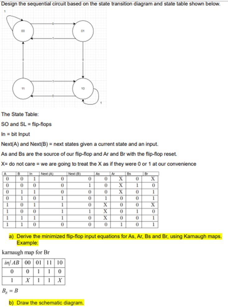
Step by step
Solved in 4 steps with 7 images
- A binary pulse counter can be constructed byinterconnecting T-type flip-flops in an appropriatemanner. Assume it is desired to construct a counterwhich can count up to 10010. a. How many flip-flops would be required?b. Sketch the circuit needed to implement this counter.Design a sequential circuit with input M and output A using the given state diagram. Reduce the number of states if necessary. Implement the circuit using SR flip-flops. Notes: Use chronological binary assignment for the states (e.g. state A = 0000, B = 0001, D = 0010 etc.) Use Q1, Q2, Q3, Q4 etc. as flip-flop variables where Q1 holds the MSB. Answer the following1. How many SR flip-flops are needed in the design? Note: For numbers 2 to 8 Type N/A if not applicable Use upper case letters, it is case sensitive Use apostrophe to indicate complemented variable For every term in the expression, follow the sequence of the alphabet, e.g., AM’Q1 In case of Q1, Q2, Q3, Q4…, arrange it in ascending order, e.g., Q2’Q42. The input equation to SR flip-flop, SQ1 =3. The input equation to SR flip-flop, RQ1 =4. The input equation to SR flip-flop, SQ2 =5. The input equation to SR flip-flop, RQ2 =6.The input equation to SR flip-flop, SQ3 =7.The input equation to SR flip-flop, RQ3 =8. The output…Show the digital circuit diagram, output waveforms and truth table of a modulo-5 up counter using toggle flip-flops and explain the working principle.
- Consider the following circuit that uses falling-edge triggered D flip-flops. Assume the Clock input, and outputs Q0, Q1, and Q2, are all initially 0. Draw waveforms for Clock, Q0, Q1, and Q2, showing at least ten Clock cycles. A. Write a table summarizing the values of Q0, Q1, and Q2 after each Clock cycle. b. Briefly explain what this circuit does at a high level, treating the Q outputs together.Design the circuit that can count from 0 ,14,6, using the suitable Flip-Flop, showing the following steps: Excitation table State table k-maps circuit diagram/designUsing two flip-flops and basic gates, construct the circuit of the given state diagram below. Provide the following: State Table, Flip-flop equations, Circuit Diagram
- Using the given equation design the equivalent D Flip-flop, state table, and state diagramGiven a sequential logic circuit expression asX(t+1) = p'X+pYY(t+1) = pX'+p'Ywhere X and Y are the two flip-flop outputs and p is the main external input.Draw the state transition table for the above-given logic function.Also, draw the state transition diagram associated with it.And What is the behavior of the circuit?For the frequency divider circuit the D-flip-flop is a CD4013 Dual D-Type flip-flop V2 is a square wave applied to the Clock input and Q is the ouput waveform. a. What is the frequency of the square wave Clock from V29? b. What is the frequency of the output pin Q? c. How many D-flip-flops are implemented in the CD4013 Chip? d. How many outputs are implemented in each D-flip-flop? List them.
- The D flip-flop is created by connecting two gated D latches serially, and inverting the CLK input to one of them. The following figure shows the internal circuit of D Flip-flop composing of two latches (L1: Master, and L2: Slave) and NOT gate. Answers the following questions. (Note: You should show all the steps) When CLK = 0 and D = 1, what are the values of N 1 and Q? N 1 = ? Explain how come. Q= ? Explain how come.Design a 2-bit binary counter using D flip-flops.Show circuit implementation using the truth table and equation from the kmap ..Suppose that you want to design a new flip-flop and name it as AMflip-flop. This AM flip-flop behaves as follows: If A = 1, the flip-flopcomplements the current state. If A =0, the next state of the flip-flopis equal to the value of M.a. Derive the characteristic table for the AM flip-flop.b. From the characteristic tables of both flip-flops, the JK and theAM (that you have derived in part a), find the equivalent valuesof J & K for each of the AM states.For example, if for A= 0, M=0, Q(‡+1) was, say, x; then youshould find the equivalent combination of J & K that producesthe same output.c. Based on the result that you have obtained in part b, show howa JK flip-flop can be converted to an AM flip-flop by addinggate(s) and inverter(s).