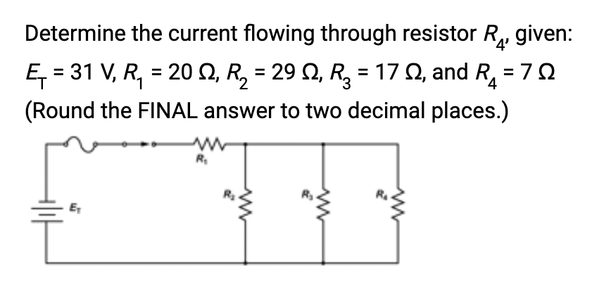
Determine the current flowing through resistor R₁, given: = 7Ω E₁ = 31 V, R₁ = 20 Q2, R₂ = 29 Q, R₂ = 17 , and R (Round the FINAL answer to two decimal places.) +||H R₁ 2 ww


Q: Find vo(t) for all t> 0 in the given circuit. Assume /= 2.5u(t) A. 192 7u(t) V 1Ω www " 1 H 0.5 F…
A: Given:a circuit, we need to find:the voltage v0(t).
Q: How is the performance of a transformer measured? Why low voltage regulation and high efficiency is…
A: The performance of a transformer, in the context of electrical engineering, is typically measured…
Q: Q4/A:For the given tie-bar system, a three phase fault occurs at the feeder supplied by the three…
A: Feeder impedance Zf=0.12ΩBase voltage 6.6kVAsked to calculate the maximum fault MVA that can be fed…
Q: 2. Let x[n] be a sequence with a DTFT X (e). For each of the following se- quences that are formed…
A: Given:we need to express:DTFT of the following sequences in terms of .
Q: A center-tapped transformer full-wave rectifier has a secondary voltage of 30 Vp. If the diodes used…
A: Maximum voltage is given as, Load resistance is given as Internal resistance is given as,
Q: If the capacitive reactance of a parallel R-C circuit is 10 times the resistance value, would the…
A:
Q: If the field current of a shunt wound d.c. motor is halved, what effect will this have on the speed?…
A: Dc shunt motor is a constant flux motor.Asked to find the speed when the field current is reduced by…
Q: Determine v(t) given an initial inductor current of 10A and an initial capacitor voltage of OV. C =…
A: The circuit diagram,The elements,
Q: 1. Design a fixed-base BJT bias circuit, similar to the one shown in Figure 1, such that VCE = 5.5…
A: The question is about designing of a self bias similar to the given circuit.
Q: Consider the Circuit shown. is = 7 sin (100+ +30) (1 TR Find a a The Ik + YL 34H 1 Find the total…
A:
Q: Determine the voltage dropped on R3, given: E₁=1596 V₁ R₁ = 93, R₂ = 47, R₂ = 38 2, and R₁ = 145 Ω…
A:
Q: 2.2 k For the series diode configuration of Fig. 2.16, determine VD. VR. and Ip
A: The given circuit is,To calculate the diode voltage, diode current and load voltage.
Q: Determine the length of a copper wire that has a cross-sectional area as 7.2 mm². The resistance and…
A: Cross sectional area Resistance Resitivity of copper
Q: An unbalanced 3-phase, 3-wire load draws the following currents: la = 162- 36.87° A; l, = 202180° A;…
A: The line-to-line voltage of a balanced three-phase source is 230 V.An unbalanced 3-phase, 3-wire…
Q: Determine the power consumed by R₁, given: '4' Ę₁ = 185 V, R₁ = 20 №, R₂ = 35 N, R₂ = 47 2, and R₁ =…
A: The given circuit is shown below.We need to determine the power consumed by R4.
Q: From the circuit down below, find average power where a=30°, ß= 60°, and frequency equal to 60Hz.…
A: The total power generated or used during a certain amount of time divided by that amount of time is…
Q: Analyze the different cable standards and specifications for various applications.
A: Cables play a critical role in various applications, and different standards and specifications are…
Q: H.W2 The single-phase half wave rectifier has R-L load with R= 59 and L= 6.5mH. The input voltage…
A: Given R-L load with R= 5 ohms and L= 6.5 mH. The input voltage Vs = 220 V at 50 Hz
Q: For the linear transformer circuit assume v(t)s = 1Vrms cos(@t)V, operated at a equency of 100Hz. is…
A: Given Data:A mutually coupled circuit with,Supply voltage Self inductances Mutual inductance Load…
Q: (6) On-delay 0.00 TO000 HH TO000 * TIM 0000 #0600 (100.00 (100.01) 0.00 100.00 100.01 60s
A: PLC ladder ON delay circuit
Q: Use nodal analysis to find the voltage V in the circuit given below, where v, = 62/5°V. 40 Ω ww j20…
A: Given circuit:voltage vs = Asked to the voltage magnitude and angle?
Q: For the logic gate network shown below, select which of the following expressions is the right one.…
A:
Q: The voltage source (V1) in the circuit is given by: v(t) = 15 * cos(5x10ft) V If L1 = 1 mH, R1 = 10…
A: The circuit diagram,The voltage,The inductor,The resistor,
Q: The current through a 0.5H coil is provided. Use the sine function to write a sinusoidal expression…
A: In this question, we need to determine the voltage across inductor. We know, Voltage across inductor…
Q: Determine the total resistance for the circuit, given: E₁=262 V, P₁ = 471 W, P₂ = 471 W, P3 = 471 W,…
A:
Q: The load on a 120V, 60 Hz supply is 5 kW (resistive), 8 kVAR (inductive), and 2 kVAR (capacitive).…
A: In this question, we need to determine the power factor, total current before power factor improve…
Q: Q13) Calculate the current I, in the following circui 100mA I + Vs R 1ΚΩ 50mA R 3 R 3 1ΚΩ"
A: Circuit diagram is given as,
Q: A 150-MHz uniform plane wave in free space is described by Hs = (4+j10)(2ax +jay)e¯jßz A/m. (a) Find…
A: e(−jβz)uniform plane wave in free space frequency (f)=150MHzHs=(4+j10)(2ax+jay)e(−jβz) A/m(a) we…
Q: 5 Find the steady-state expression for v, in the circuit = = 200 cos 5000t mA. of Fig. P9.26 if i g…
A: Using current division rule, find the current through the 240 ohms resistor. By ohms law , voltage…
Q: 6- Find the resistance value of R to receive the maximum power from the circuit it is connected to.…
A: The given circuit is,To determine the value of R to receive the maximum power from the circuit.
Q: Discuss the different types of transistors used in microchips and how they work.
A: Microchips, also known as integrated circuits, are miniature electronic devices that house…
Q: 3.) Use Mesh Analysis to determine the values of the mesh currents and vx. [C02] 1252 – ), แกรี่ โ…
A: Given:a circuit, we need to find:mesh currents and voltage vx using mesh analysis.
Q: In the circuit given below, G=2 S. Calculate v₁, v2, and v3. 2 A V1 G The value of vis The value of…
A: The circuit diagram,
Q: 9.15 a) Show that, at a given frequency w, the circuits in Fig. P9.15(a) and (b) will have the same…
A: The given circuit diagram is shown below,
Q: Q4/A:For the given tie-bar system, a three phase fault occurs at the feeder supplied by the three…
A: Feeder impedance Zf=0.12ΩBase voltage 6.6kVAsked to calculate the maximum fault MVA that can be fed…
Q: Consider the position control system given below. Determine the value of K such that the steady…
A:
Q: I want to make a circuit measuring the Beta of a transistor on my breadboard, which gives me the…
A: It is asked to draw a circuit measuring the '' of a transistor on a breadboard, that gives the ''…
Q: The amplifier in the circuit below is driven by a signal generator V, with a small sine wave signal…
A:
Q: State the difference between type BIT and type STD_ STD_LOGIC have so many values?
A: we need to:state the difference between type BIT and type STD_LOGIC.explain the reason why STD_LOGIC…
Q: Determine the current flowing through resistor R₁, given: E₁=277 V, R₁ = 212, R₂ = 62, R₂ = 132, and…
A: The circuit diagram,
Q: 10) Let's consider a discrete-time LTI system initially at rest and defined by the equation y[n] +…
A: The difference question is given as ...(1)The input x(n) is given as
Q: Find the convolution of the following sequences using matrix multiplication method. How would you…
A: The discrete sequences are x[n]={2↑,−1,0,4}.h[n]={5↑,3,−7,6}.We need to calculate the convolution of…
Q: For the circuit below, find the transfer function H(w) = Vo/Vi. Vi 10 с L R +
A: The given circuit isWe need to find the transfer function H(ω)=VoVi.
Q: Calculate the current total complex power and power factor ST= ST= pf = untis lagging, leading, or…
A: Voltage V = 240VFrequency f = 60 Hz The loads areLoad 1: 10 kVA @ pf = 0.55 laggingLoad 2: 5 kVA @…
Q: The equivalent block diagram for a system is shown below R(S) + K + + 10 s + 10 10 10 S² Calculate…
A: We need to calculate the range of K and stability .
Q: H.W1 The single-phase full wave rectifier has a purely resistive load of R, determine: a) The…
A:
Q: What is the ladder logic equivalent of the following gate logic?
A: For the given logic diagram the equivalent ladder logic diagram needs to be identified.
Q: H.W4 The diode in the single-phase half wave rectifier has a reverse recovery time of t₁ = 150µsec…
A: Given data:
Q: Which figure below shows the correct vector relationship between voltage and current in a series LC…
A: The phasors,
Q: Determine the current flowing through resistor R₁ given: Ę₁ = 28 V₁ R₁ = 30 ≤, R₂ = 13 №, R₂ = 20 N,…
A: Circuit diagram is given as,
Determine the current flowing through resistor R4

Step by step
Solved in 3 steps with 3 images

- Use the following circuit diagram of a DC parallel circuit for calculations. Known: VAB = 14 V, R1 = 56 Ohm, R2 = 84 Ohm, and R3 = 134 Ohm. Calculate the current through path 1(I1). Keep three decimals for accuracy.1) Consider the circuit shown with a battery pack and three similar lightbulbs, with two ammeters included in the circuit, before and after the lightbulbs. How do you expect the readings of the two ammeters to compare? I1 > I2 I1 = I2 I1 < I2three resistors of 10,12,& x ohms, respectively are connected in parallel across a constant current source of 8A, Determine "x" if this resistor draws 2.133333....A
- Question 3 In the circuit below, the current io = 2A. Part (A) Find i1.Part (B) Find the power dissipated in each resistor.Part (C) Verify that the total power dissipated in the circuit equals the power provided by thevoltage source.Please answer it within 30 minutes.I will upvote! (a) Can the circuit shown in the figure above be reduced to a single resistor connected to a battery?Explain. (b) Calculate the current I1,I2 and I3 .The following equations describe an electric circuit: -I1 (220 Ω) + 5.80 V - I2 (370 Ω) = 0 -I2 (370 Ω) + I3 (150 Ω) - 3.10 V = 0 I1 + I3 - I2 = 0(a) Draw a diagram of the circuit. (b) Calculate the unknowns and identify the physical meaning of each unknown.
- Topic: Ohm's Law, Current, Voltage and Resistance Concepts Kindly answer the problem. Thank you.Determine the power absorbed by element X of the circuit, if it is: a 4 k resistor; (b) a separate 20 mA current source, with downward reference arrow; (c) a dependent current source, with downward reference arrow, marked 2ix; (d) an independent 60V voltage source, reference + at the top.Calculate the theoretical Voltage drop across R1. Calculate the theoretical Voltage drop across R2. S1 Voltage 5.37v Tp-1 Voltage 5.37v Tp-2 Voltage 2.14v Ammeter Current 11.7ma R1 Resistance measured 273ohms R1 Resistance value based on the color code Red,violet,brown,gold R1 color code = 270 R2 Resistance measured 183ohms R2 Resistance value based on the color code Brown ,violet,brown,gold R2 color code = 180ohms
- Consider the following circuit and calculate:a. The voltage drops across the 5Ω resistor? b. The current passing through the 30Ω resistor?c. The power developed in 7 Ω resistor? d. The power developed in 18Ω resistor? e. The voltage at point X with respect to the earth? (question in more detail in picture attached)2) Find the currents and voltages in the circuit shown Figure 2.Depending on voltmeter/ammeter terminal connection to the components, you might find different signed voltage and currents values for the same component. This causes different signed power values for the same components therefore we cannot state whether components generate or absorb power. What is your solution to this chaos? **please type it using keyboard NOT handwriting**