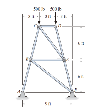
Determine the force in each element of the reinforcement and indicate if the elements are in tension or in compression.


Q: Determine the force in each member of the truss and indicate whether the members are in tension of…
A: Given: TO determine: Forces in each member
Q: If the maximum force that any member can support is SOO N in tension and 700 N in compression,…
A:
Q: Determine the force of each element Indicate if the elements are in tension or in compression
A:
Q: termine the forces in members BE and CE of the loaded truss. The forces are positive if in tension,…
A:
Q: Determine the force in member BC of the loaded truss. The force is positive if in tension, negative…
A: Consider upward & horizontal forward force as (+)ve and downward force as (-)ve. Assume…
Q: Determine the force in each member of the truss, and state if the members are in tension or…
A: downward force = 4 KN Using sign convection
Q: The truss is supported by a pin at A and a roller at B. Determine the support reactions. 60 kN
A:
Q: Members AC and AB support the 300-lb crate. Determine the tensile force developed in member (AB).
A:
Q: Determine the force in each member of the truss, and state if the members are in tension or…
A:
Q: Determine the force in member BE of the loaded truss. The force is positive if in tension, negative…
A:
Q: Members AC and AB support the 150-lb crate. Determine the tensile force developed in member (AB).
A:
Q: Determine the force in each member of the loaded truss. The force is positive if in tension,…
A:
Q: Determine the force in each member of the loaded truss. The forces are positive if in tension,…
A:
Q: Determine the force in each member of the truss, and state if the members are in tension or…
A:
Q: Determine the force in member BE of the loaded truss. The force is positive if in tension, negative…
A:
Q: Members AC and AB support the 500-lb crate. Determine the tensile force developed in member (AB).
A: Correct ans is a. None of these
Q: Determine the force in member BE of the loaded truss. The force is positive if in tension, negative…
A:
Q: a) Determine the force in members KJ, KD, and CD. Enter a postive value if the member is in tension…
A:
Q: Q1) Determine the force in each member of the truss, and state if the members are in tension or…
A: Given Data- A Truss is Given , on which different force are acting We have to find force in each…
Q: in tension or compression. The supports at A and 3 m -2 m- 1 m 1m Determine the forces in each…
A:
Q: The crate has a weight of 550 lb. Determine the force in each supporting cable.
A: Given data Weight = 550 lb
Q: Determine the force in member AE of the loaded truss. The force is positive if in tension, negative…
A:
Q: Determine the axial forces in the members if F = 9.75 kN.
A:
Q: Determine the magnitude of the horizontal force F and the support reactions at . If the cord CB ean…
A: Given: To determine: Reaction force at pin A
Q: determine the forces in all of the members marked with a checkmark () using the method of sections.…
A:
Q: Determine the force in member BE of the loaded truss. The force is positive if in tension, negative…
A: Determine the length of bar CE by using a similar triangle. CEAG=DCDACE= 6 m18 m·7 m=73 m Determine…
Q: Determine the force in each member of the truss and state if the members are in tension or…
A: Given:-Force at B=4 kNForce at A=5 kNTo find:-Forces in each member
Q: F1 = 10 kN Determine the force in each member and state whether it is in tension or compression
A:
Q: Determine the force on each element of the reinforcement and determine if the elements are in…
A:
Q: 4 kN 3 m 3 m -3 m BY D 3 m 5 m 5 kN
A: GIVEN DATA A PLANE TRUSS GIVEN WE HAVE TO FIND FORCE IN EACH MEMBER OF TRUSS
Q: Determine the force in each member of the truss, and state if the members are in tension or…
A: Free body diagram FREE BODY DIAGRAM is a diagram of the system which represents all the forces…
Q: If it is known that the center pin A supports one-half of the vertical loading shown, determine the…
A: It is given that the center pin A supports the one half of the vertical loading. So, from…
Q: Determine the force in each member of the loaded truss. The force is positive if in tension,…
A:
Q: Determine the force in each member of the truss, and state if the members are in tension or…
A: Given P = 800 lb To find Force at each truss
Q: Determine the force in each member of the loaded truss as a result of the hanging weight W = 265 lb.…
A: Given data, W = weight of the hanging block = 265 lb Point A is hinge support. So, one vertical…
Q: Determine the force in each member * .of the loaded truss 6m 5m 5m 5000 N 45 B
A: Mechanical Equilibrium: A body is said to be in mechanical equilibrium if it satisfies the following…
Q: Determine the magnitude of the horizontal force F and the support reactions at pin A.If the cord CB…
A:
Q: Determine (approximately) the force (k) in member FH of the portal frame. Assume all members of the…
A:
Q: Determine the forces in members BE, BD and CD if the weight W = 200 N. Use the sign - if the force…
A:
Q: Determine the force in member BE of the loaded truss. The force is positive if in tension, negative…
A:
Q: 2 m 3 m C 5 kN B
A: To find: The force in each member of the truss. FBD: The free body diagram shown below:
Q: Determine the force in member BE of the loaded truss. The force is positive if in tension, negative…
A:
Q: Determine all the bar forces. State whether the member is tension or compression.
A:
Q: Determine the force in each member of the truss and state if the member are in tension or…
A:
Q: Problem. If the bucket and its contents have a total weight of 20 lb, determine the force in the…
A:
Q: Determine the force in each member of the truss and state if the members are in tension or…
A:
Q: Determine the force in member BE of the loaded truss. The force is positive if in tension, negative…
A:
Q: Determine the force in member BE of the loaded truss. The force is positive if in tension, negative…
A:
Determine the force in each element of the reinforcement and indicate if the elements are in tension or in compression.


Trending now
This is a popular solution!

Step by step
Solved in 4 steps with 4 images

- A safety valve on the top of a tank containing steam under pressure p has a discharge hole of diameter d(see figure). The valve is designed to release the steam when the pressure reaches the value Pmax If the natural length of the spring, is L and its stiffness is k, what should be the dimension ft of the valve? (Express your result as a formula for h.)Repeat Problem 11.2-14 using L = 12 ft, ß = 0.25 kips/in., ßRl= 1.5ßL2, and ßR2= 2 ßR1.The hollow drill pipe for an oil well (sec figure) is 6,2 in. in outer diameter and 0.75 in. in thickness. Just above the bit, the compressive force in the pipe (due to the weight of the pipe) is 62 kips and the torque (due to drilling) is 185 kip-in. Determine the maximum tensile, compressive, and shear stresses in the drill pipe.
- Two steel wines support a moveable overhead camera weighing W = 28 lb (see figure part a) used For close-up to viewing of field action at sporting, events. At some instant, wire I is at an angle a = 22° to the horizontal and wire 2 is at angle fi = 40°. Wires I and 2 have diameters of 30and 35 mils, respectively. (Wire diameters are often expressed in mils; one mil equals 0.001 in.) (a) Determine the tensile stresses s and s2 in the two wires. (b) If the stresses in wires 1 and 2 must be the same, what is the required diameter of wire 1 ? (c) To stabilize the camera for windy outdoor conditions, a third wire is added (see figure part b). Assume the three wires meet at a common point coordinates (0, 0. 0) above the camera at the instant shown in figure part b. Wire I is attached to a support at coordinates (75 ft, 48 ft, 70 Ft). Wire 2 is supported at (-70 ft. 55 ft, 80 Ft). Wire 3 is supported at (-10 ft. -85 Ft, 75 ft). Assume that all three wires have a diameter of 30 mils. Find the tensile stresses in all three wiresThe force P3 to make it to equilibrium in kN is The Stress in section 1 in N/mm2 is The Compressive Stress in section 2 in N/mm2 is The stress in section 3 in N/mm2 is The total change in length in x10-3 mm isᴀ 10-ᴛᴏɴ ᴠᴀᴘᴏʀ ᴄᴏᴍᴘʀᴇꜱꜱɪᴏɴ ʀᴇꜰʀɪɢᴇʀᴀᴛɪᴏɴ ꜱʏꜱᴛᴇᴍ ɪꜱ ᴛᴏ ᴇᴠᴀᴘᴏʀᴀᴛᴇ ʀ-12 ᴀᴛ -20°ᴄ ᴀɴᴅ ᴛᴏᴄᴏɴᴅᴇɴꜱᴇ ɪᴛ ᴀᴛ 40°ᴄ. ᴛʜᴇ ᴛᴡɪɴ-ᴄʏʟɪɴᴅᴇʀ ᴠᴇʀᴛɪᴄᴀʟ ᴄᴏᴍᴘʀᴇꜱꜱᴏʀ ɪꜱ ᴛᴏ ʀᴜɴ ᴀᴛ 900 ʀᴘᴍ; ɪᴛ ɪꜱ ꜱɪɴɢʟᴇ ᴀᴄᴛɪɴɢ, ʜᴀꜱ ᴛʜᴇʙᴏʀᴇ ᴇQᴜᴀʟ ᴛᴏ ᴛʜᴇ ꜱᴛʀᴏᴋᴇ, ᴀɴᴅ ʜᴀꜱ 2% ᴄʟᴇᴀʀᴀɴᴄᴇ. ᴠᴀᴘᴏʀ ᴇɴᴛᴇʀꜱ ᴛʜᴇ ᴄᴏᴍᴘʀᴇꜱꜱᴏʀ ᴀᴛ -10°ᴄ ᴀɴᴅ ʟɪQᴜɪᴅ ᴇɴᴛᴇʀꜱ ᴛʜᴇᴇxᴘᴀɴꜱɪᴏɴ ᴠᴀʟᴠᴇ ᴀᴛ 30°ᴄ.Required:ᴡʜᴀᴛ ʀᴇꜰʀɪɢᴇʀᴀᴛɪᴏɴ ꜰʟᴏᴡ ʀᴀᴛᴇ ɪꜱ ʀᴇQᴜɪʀᴇᴅ?ᴡʜᴀᴛ ᴡᴏᴜʟᴅ ʙᴇ ᴛʜᴇ ʙᴏʀᴇ ᴀɴᴅ ꜱᴛʀᴏᴋᴇ ᴏꜰ ᴛʜᴇ ᴄᴏᴍᴘʀᴇꜱꜱᴏʀ?ᴡʜᴀᴛ ᴘᴏᴡᴇʀ ɪꜱ ʀᴇQᴜɪʀᴇᴅ ʙʏ ᴛʜᴇ ᴄᴏᴍᴘʀᴇꜱꜱᴏʀ?ᴡʜᴀᴛ ɪꜱ ᴛʜᴇ Qᴜᴀɴᴛɪᴛʏ ᴏꜰ ᴛʜᴇ ᴄᴏᴏʟɪɴɢ ᴡᴀᴛᴇʀ ʀᴇQᴜɪʀᴇᴅ ɪɴ ᴛʜᴇ ᴄᴏɴᴅᴇɴꜱᴇʀ ꜰᴏʀ ᴀ 8-ᴅᴇɢʀᴇᴇ ɪɴᴄʀᴇᴀꜱᴇ ɪɴ ᴛᴇᴍᴘᴇʀᴀᴛᴜʀᴇ?
- ɪɴ ᴀ ᴄᴏɴᴠᴇɴᴛɪᴏɴᴀʟ ʀᴇꜰʀɪɢᴇʀᴀᴛɪᴏɴ ᴄʏᴄʟᴇ ᴡʜɪᴄʜ ᴜꜱᴇꜱ ꜰʀᴇᴏɴ-12 ᴀꜱ ᴛʜᴇ ʀᴇꜰʀɪɢᴇʀᴀɴᴛ, ᴛʜᴇ ᴛᴇᴍᴘᴇʀᴀᴛᴜʀᴇᴏꜰ ᴛʜᴇ ᴇᴠᴀᴘᴏʀᴀᴛɪɴɢ ꜰʟᴜɪᴅ ɪꜱ -20°ᴄ. ɪᴛ ʟᴇᴀᴠᴇꜱ ᴛʜᴇ ᴇᴠᴀᴘᴏʀᴀᴛᴏʀ ᴀꜱ ꜱᴀᴛᴜʀᴀᴛᴇᴅ ᴠᴀᴘᴏʀ ᴀᴛ -20°ᴄ ᴀɴᴅ ᴇɴᴛᴇʀꜱ ᴛʜᴇ ᴄᴏᴍᴘʀᴇꜱꜱᴏʀ. ᴛʜᴇ ᴘʀᴇꜱꜱᴜʀᴇ ɪɴ ᴛʜᴇ ᴄᴏɴᴅᴇɴꜱᴇʀ ɪꜱ 1.30 ᴍᴘᴀ. ᴛʜᴇ ʟɪQᴜɪᴅ ʟᴇᴀᴠᴇꜱ ᴛʜᴇ ᴄᴏɴᴅᴇɴꜱᴇʀ ᴀɴᴅ ᴇɴᴛᴇʀꜱ ᴛʜᴇ ᴇxᴘᴀɴꜱɪᴏɴ ᴠᴀʟᴠᴇ ᴀᴛ 40°ᴄ. ɪᴛ ɪꜱ ᴘʀᴏᴘᴏꜱᴇᴅ ᴛᴏ ᴍᴏᴅɪꜰʏ ᴛʜɪꜱ ᴄʏᴄʟᴇ ʙʏ ᴀᴅᴅɪɴɢ ᴀ ʜᴇᴀᴛ ᴇxᴄʜᴀɴɢᴇʀ ᴛʜᴀᴛ ᴡᴏᴜʟᴅ ꜱᴜᴘᴇʀʜᴇᴀᴛ ᴛʜᴇ ꜱᴜᴄᴛɪᴏɴ ᴠᴀᴘᴏʀ ᴛᴏ 25°ᴄ.Required:-ᴄᴏᴍᴘᴀʀᴇ ᴛʜᴇ ᴄᴏᴇꜰꜰɪᴄɪᴇɴᴛ ᴏꜰ ᴘᴇʀꜰᴏʀᴍᴀɴᴄᴇ ᴏꜰ ᴛʜᴇꜱᴇ ᴛᴡᴏ ᴄʏᴄʟᴇꜱ.-ᴡʜᴀᴛ ɪꜱ ᴛʜᴇ ᴛᴇᴍᴘᴇʀᴀᴛᴜʀᴇ ᴏꜰ ᴛʜᴇ ʀᴇꜰʀɪɢᴇʀᴀɴᴛ ᴇɴᴛᴇʀɪɴɢ ᴛʜᴇ ᴇxᴘᴀɴꜱɪᴏɴ ᴠᴀʟᴠᴇ ᴡɪᴛʜ ᴛʜᴇ ʜᴇᴀᴛᴇxᴄʜᴀɴɢᴇʀ?-ꜰᴏʀ ᴀ ʟᴏᴀᴅ ᴏꜰ 50 ᴋᴡ, ᴅᴇᴛᴇʀᴍɪɴᴇ ᴛʜᴇ ᴠᴏʟᴜᴍᴇ ꜰʟᴏᴡ ʀᴀᴛᴇ ꜰᴏʀ ʙᴏᴛʜ ᴄʏᴄʟᴇꜱ.5 - note: ignore weight of the bar.A) ( - 6/7)T(CB) + A(y)=0 (A=reaction force at A, A(x), A(y), A(z) are components of force A)B) (2/7)T(CB)+A(x)=392 (A=reaction force at A, A(x), A(y), A(z) are components of force A)C) A(x)=2A(y) (A=reaction force at A, A(x), A(y), A(z) are components of force A)D) A(x)=5A(z) (A=reaction force at A,A(x), A(y), A(z) are components of force A)Question 4A close-coiled helical spring is to have a stiffness of 90 kN/m and is to exert a maximum force of 3.7 kN. If the mean diameter of the coils is 80 mm, and the maximum stress is not to exceed 300 MPa, calculate the required number of coils and the diameter of the steel rod from which the spring should be made (G=80 GPa).
- Two springs, as shown are to carry a load of 90 kN. The spring on the left is the larger spring. Spring specifications are as follows: wire diameter=25 mm, outside coil diameter= 230mm, no. of active coils=8; and wire diameter=20 mm, outside coil diameter= 170mm, no. of active coils=20. Take G= 79 GPa. Determine the force exerted by each spring and the stress induced in each.9-8kN stress/force on the AB rope holding the base station shown below There are. In order for the net force at point A of this base station to be downward What is the stress/force that should be on the AC rope? A) 5556 N C) 7356 N B) 8200 N D) 3648 N E) 1228 N4kN/m uniform spring load h = 2b allowable normal stress 12MPa h(min) = ?