
Concept explainers
Videos
Two steel wines support a moveable overhead camera weighing W = 28 lb (see figure part a) used For close-up to viewing of field action at sporting, events. At some instant, wire I is at an angle a = 22° to the horizontal and wire 2 is at angle fi = 40°. Wires I and 2 have diameters of 30and 35 mils, respectively. (Wire diameters are often expressed in mils; one mil equals 0.001 in.)
(a) Determine the tensile stresses s and s2 in the two wires.
(b) If the stresses in wires 1 and 2 must be the same, what is the required diameter of wire 1 ?
(c) To stabilize the camera for windy outdoor conditions, a third wire is added (see figure part b). Assume the three wires meet at a common point coordinates (0, 0. 0) above the camera at the instant shown in figure part b. Wire I is attached to a support at coordinates (75 ft, 48 ft, 70 Ft). Wire 2 is supported at (-70 ft. 55 ft, 80 Ft). Wire 3 is supported at (-10 ft. -85 Ft, 75 ft). Assume that all three wires have a diameter of 30 mils. Find the tensile stresses in all three wires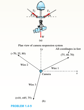

Trending nowThis is a popular solution!

Chapter 1 Solutions
Mechanics of Materials (MindTap Course List)


- The main cables of a suspension bridge (see figure part a) follow a curve that is nearly parabolic because the primary load on the cables is the weight of the bridge deck, which is uniform in intensity along the horizontal. Therefore, represent the central region AOB of one of the main cables (see part b of the figure) as a parabolic cable supported at points A and B and carrying a uniform load of intensity q along the horizontal. The span of the cable is L, the sag is /i, the axial rigidity is EA\ and the origin of coordinates is at mid span. (a) Derive the following formula for the elongation of cable AOB shown in part b or the figure: (b) Calculate the elongation 5 of the central span of one of the main cables of the Golden Gate Bridge for which the dimensions and properties are L = 4200 ft,h = 470 ft, q = 12,700 lb/ft, and E = 23,300,000 psi The cable consists of 27,572 parallel wires of diameter 0.196 in. Hint: Determine the tensile force Tal any point in the cable from a free-body diagram of part of the cable; then determine the elongation of an element of the cable of length ds: finally, integrate along the curve of the cable to obtain an equation for the elongation £.arrow_forwardA large precast concrete panel for a warehouse is raised using two sets of cables at two lift lines, as shown in the figure part a. Cable 1 has a length L1 = 22 Ft, cable 2 has a length L2= 10 ft, and the distance along the panel between lift points Band D is d = 14 ft (see figure part b). The total weight of the panel is W = 85 kips. Assuming the cable lift Forces F at each lift line are about equal, use the simplified model of one half of the panel in figure part b to perform your analysis for the lift position shown. Find the required cross-sectional area AC of the cable if its breaking stress is 91 ksi and a factor of safety of 4 with respect to failure is desired.arrow_forwardA steel riser pipe hangs from a drill rig located offshore in deep water (see figure). (a) What is the greatest length (meters) it can have without breaking if the pipe is suspended in the air and the ultimate strength (or breaking strength) is 550 MPa? (b) If the same riser pipe hangs from a drill rig at sea, what is the greatest length? (Obtain the weight densities of steel and sea water from Table M, Appendix I. Neglect the effect of buoyant foam casings on the pipe.)arrow_forward
- A vertical bar is loaded with axial loads at points B, C, and D. as shown in the figure. The bar is made of steel with a modulus of elasticity E = 29,000 ksi., The bar has a cross-sectional area of 8.24 in2. Calculate the displacements at points B, C, and D. Ignore the weight of the bararrow_forwardA bar ABC revolves in a horizontal plane about a vertical axis at the midpoint C (see figure). The bar, which has a length 2L and crass-sectional area A, revolves at constant angular speed at. Each half of the bar (AC and BC) has a weight W, and supports a weight W2at its end. Derive the following formula for the elongation of one-half of the bar (that is. the elongation of either AC ar BC). =L223gEA(w1+3w2) in which E is t he modulus of elasticity of the material of the bar and g is the acceleration of gravity.arrow_forwardA safety valve on the top of a tank containing steam under pressure p has a discharge hole of diameter d(see figure). The valve is designed to release the steam when the pressure reaches the value Pmax If the natural length of the spring, is L and its stiffness is k, what should be the dimension ft of the valve? (Express your result as a formula for h.)arrow_forward
- A uniform bar AB of weight W = 25 N is supported by two springs, as shown in the figure. The spring on the left has a stiffness k[= 300 N/m and natural length Lt=250 mm. The corresponding quantities for the spring on the right are k2= 400 N/m and L^ = 200 mm. The distance between the springs is L = 350 mm, and the spring on the right is suspended from a support that is a distance it = SO mm below the point of support for the spring on the left. Neglect the weight of the springs. (a) At what distance x from the left-hand spring (figure part a) should a load P = 18 N be placed in order to bring the bar to a horizontal position? (b) If P is now removed, what new value of k{is required so that the bar (figure part a) will hang in a horizontal position underweight If? (c) If P is removed and kt= 300 N/m. what distance b should spring ktbe moved to the right so that the bar (figure part a) will hang in a horizontal position under weight II"? (d) If the spring on the left is now replaced by two springs in series (kt= 300 N/m, kt) with overall natural length Lt= 250 mm (see figure part b). what value of k; is required so that the bar will hang in a horizontal position under weight IF?arrow_forwardA steel post (E=30×106) having thickness t = 1/8 in. and height L = 72 in. support a stop sign (see figure), where s = 12.5 in. The height of the post L is measured from the base to the centroid of the sign. The stop sign is subjected to wind pressure p = 20 lb/ft2 normal to its surface. Assume that the post is fixed at its base. What is the resultant load on the sign? (Sec Appendix E, Case 25, for properties of an octagon, n =8.) What is the maximum bending stress in the post? Repeat part (b) if the circular cut-outs arc eliminated over the height of the post.arrow_forwardA rigid bar AB having a mass M = 1.0 kg and length L = 0.5 m is hinged at end A and supported at end B by a nylon cord BC (see figure). The record has cross-sectional area A = 30 mm2. length b = 0.25 m. and modulus of elasticity E = 2.1 GPa. If the bar is raised to its maximum height and then released, what is the maximum stress in the cord?arrow_forward
- A hollow circular pipe (see figure} support s a load P that is uniformly distributed around a cap plate at the top of the lower pipe. The inner and outer diameters of the upper and lower parts of the pipe are d1= 50 mm, d2= 60 mm, rf3 = 57 mm, and d1= 64 mm, respectively. Pipe lengths are Lt= 2 m and L, = 3 m. Neglect the self-weight of the pipes. Assume that cap plate thickness is small compared to I, and E,. Let E = 110 MPa. (a) If the tensile stress in the upper part is d = 10.5 MPa. what is load PI Also, what are reactions ft, at the upper support and R-, at the lower support? What is the stress ar(MPa) in the lower part? (b) Find displacement S(mm) at the cap plate. Plot the axial force diagram (AFD) [Ar(.f)] and axial displacement diagram (ADD)[5(.t)]. (c) Add the uniformly distributed load q along the censorial axis of pipe segment 2. Find q (kN/m) so that It, = 0. Assume that load P from part (a) is also applied.arrow_forwardA steel riser pipe hangs from a drill rig located offshore in deep water (see figure). Separate segments are joined using bolted flange plages (see figure part b and photo). Assume that there are six bolts at each pipe segment connection. Assume that the total length of the riser pipe is L = 5000 ft: outer and inner diameters are d2= l6in.and d1= 15 in.; flange plate thickness t1= 1.75 in.; and bolt and washer diameters are db= 1.125 in..and dW. = 1.875 in., respectively. (a) If the entire length of the riser pipe is suspended in air. find the average normal stress a in each bolt, the average bearing stress abbeneath each washer, and the average shear stress t through the flange plate at each bolt location for the topmost bolted connection. (b) If the same riser pipe hangs from a drill rig at sea. what are the normal, bearing, and shear stresses in the connection? Obtain the weight densities of steel and sea water from Table I-1. Appendix I. Neglect the effect of buoyant foam casings on the riser pipearrow_forwardA bimetallic bar (or composite bar) of square cross sec lion with dimensions 2b X lb is construe ted of two different metals having module of elasticity E2and E2(see figure). The two parts of the bar have the same cross-sectional dimensions. The bar is compressed by forces P acting through rigid end plates. T h e line of action of t he loads has an eccentricity e of such magnitude that each part of the bar is stressed uniformly in compression. (a) Determine the axial forces Ptand P2in the two parts of the bar. (b} Determine the eccentricity e of the loads. (c) Determine the ratio C|/tr2 of the stresses in the two parts of the bar.arrow_forward
 Mechanics of Materials (MindTap Course List)Mechanical EngineeringISBN:9781337093347Author:Barry J. Goodno, James M. GerePublisher:Cengage Learning