Determine the force in member JH and BH for the truss loaded and supported as shown in figure (3). Does the statically indeterminacy of the supports affect your calculation? Why?
Determine the force in member JH and BH for the truss loaded and supported as shown in figure (3). Does the statically indeterminacy of the supports affect your calculation? Why?

International Edition---engineering Mechanics: Statics, 4th Edition
4th Edition
ISBN:9781305501607
Author:Andrew Pytel And Jaan Kiusalaas
Publisher:Andrew Pytel And Jaan Kiusalaas
Chapter5: Three-dimensional Equilibrium
Section: Chapter Questions
Problem 5.26P: The figure shows the FBD of a portion of the space truss shown in Fig. P5.25. Use this FBD to find...

Related questions
Question
i need the answer quickly
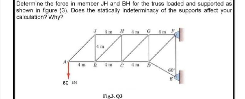
Transcribed Image Text:Determine the force in member JH and BH for the truss loaded and supported as
shown in figure (3). Does the statically indeterminacy of the supports affect your
calculation? Why?
4m H4m G4m F
4 m
4 m B 4 m
C 4m
D
60
60 kN
Fig.3. Q3
Expert Solution
This question has been solved!
Explore an expertly crafted, step-by-step solution for a thorough understanding of key concepts.

Step by step
Solved in 2 steps with 2 images

Recommended textbooks for you
International Edition---engineering Mechanics: St…
Mechanical Engineering
ISBN:
9781305501607
Author:
Andrew Pytel And Jaan Kiusalaas
Publisher:
CENGAGE L
International Edition---engineering Mechanics: St…
Mechanical Engineering
ISBN:
9781305501607
Author:
Andrew Pytel And Jaan Kiusalaas
Publisher:
CENGAGE L