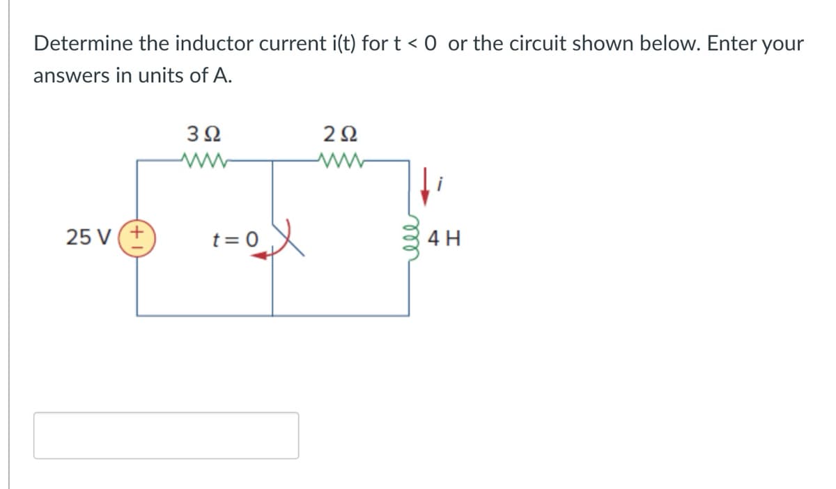
Determine the inductor current i(t) for t < 0 or the circuit shown below. Enter your answers in units of A. 302 202 www ww 25 V(+ t=0✗ ell 4H


Q: please draw a pmos reverse voltage protection circuit with a FDN308P, max voltage is 8.4V and max…
A: Schematic diagram of the PMOS reverse voltage protection circuit using the FDN308P MOSFET.Here's a…
Q: In the circuit shown in (Figure 1), the voltage across the 2.00 resistor is 16.0 V. The battery has…
A: Approach to solving the question: Detailed explanation: Examples: Key references:
Q: please help me make this into a hybrid pi model.
A:
Q: Please do not rely too much on chatgpt, because its answer may be wrong. Please consider it…
A: Actual method: Convert the above equation to a k-map. 2nd method:
Q: Q6. A circuit is required to convert a DC supply voltage of 12 Volts to 5 volts using a Zener diode.…
A: The objective of the question is to design a voltage regulator circuit using a Zener diode that can…
Q: In electrical parameters, what is representing the BJT's output characteristics?make a plot to…
A: A Bipolar Junction Transistor (BJT) is a type of semiconductor device used in electronic circuits…
Q: Q1: If X and Y are jointly continuous random variables with probability density function f(x,y)…
A: The covariance of the random variables X and Y is: Cov(X,Y)=[∫−11∫01xy(x+y) dx dy]−E(X)E(Y)…
Q: After being open for a long time the switch is closed. If the current is I = 2 A just after closing…
A: Based on the image you sent, it appears to be a circuit containing a dependent voltage source and a…
Q: Exercise 2. In the circuit below: a) Find the measures by the ammeters A, A2 and the voltmeter VR,…
A:
Q: A filter is a device or process that removes some unwanted components or features from a signal. A…
A: Step 1: From the given, To identify the graphical representation of Low-Pass filter,we use it's…
Q: Question 2 A negatively charged particle is moved from point 1 to point 2, as displayed in the…
A: The electric potential energy increases. This is because opposite charges attract each other, so the…
Q: D.C. Supply Voltage Field Current, IF (A) 3.5 V Load Torque, T = 0 N.m. Shaft Speed, Nm (rpm) 662…
A:
Q: no ai, plz give step by step
A: Step 1:
Q: 8.5 A balanced wye-connected load of (4 + j3) Q2 is connected across a three-phase source of 173 V…
A: Step 1: For star connections, phase and line currents are equal whereas line voltages are 1.732…
Q: The swtich has been in position A for a long time and it is brought to position B at t=0 s, making…
A: Given:with Vs=30 V and the switch has been in position in A for long time and it is connected to…
Q: Question #3 A resistor, denoted as R,, is added in series with the inductor in the circuit in Fig.…
A: Step 1: Step 2: Step 3: Step 4: Step 5:
Q: None
A: If you are having doubt in any step please comment here. Thank you
Q: Question 1 I need the answer to be supported by a diagram or an equation 1. What is the purpose of…
A: 1.The purpose of lamination the core of the transformer is to reduce the Eddy current losses in the…
Q: Do it
A: ANSWER:The correct answer is B) Two EXPLANTION:Option B) Two is correct because when four 1s are…
Q: Check the controlibility of the following systems:
A: Step 1: Step 2:Step 3:Step 4:
Q: Q6. A circuit is required to convert a DC supply voltage of 12 Volts to 5 volts using a Zener diode.…
A: Step 1:Step 2: Step 3: Step 4:
Q: no ai,
A: To derive the average bit error rate (BER) for noncoherent Binary Amplitude Shift Keying (BASK),…
Q: 4. Define voltage regulation of a transformer? 5. Full load copper loss in a transformer is 1600W.…
A: Since you have posted multiple questions , we will provide the solution only to the first three…
Q: Draw sechematic diagram for delta/delta
A:
Q: (a) Given the filter network below, determine the transfer function G₁ (jw), sketch the magnitude…
A:
Q: Q2: For the pole-zero diagram shown in Figure below. Calculate and plot the magnitude frequency and…
A:
Q: Fill out the values in the table frequency, f (kHz) Results from in-Lab measurements…
A: Step 1: Step 2: Step 3: Step 4:
Q: Write equations for the waveforms of Figure. Express the phase angle indegrees. Here the answers…
A: Step 1: Step 2: Step 3: Step 4:
Q: 1.The voltage across a 10 resistor is: v(wt) = to 30 sin wt. a. Find the sinusoidal expression for…
A: In a resistor, the voltage and current are in same phase.There is no angle difference between…
Q: 1. Determine i and v in the circuit shown for R = 1 k and Vin = 15 V. Assume the diodes are ideal…
A: Step 1: ko Step 2: Step 3:
Q: 1. Use Kirchhoff's laws to calculate the current flowing through the 30 2 resistor in FIGURE 1…
A: The circuit diagram,
Q: Q2) Consider a control system has open loop transfer function as: G(s) = 50 s(s+ 1)(s+4) (s + 5) The…
A: Step 1: Step 2: Step 3: Step 4:
Q: Please answer in typing format
A: The steady state condition refers to the state of a circuit or system when all voltages, currents,…
Q: Develop a flowchart for the digital compensator below. Gc(Z) = (X(Z)/E(Z)=(Z+0.5)/(Z2 - 0.5Z + 0.7)
A:
Q: Can you provide me the detail answer about alexander electric circuits problem 4.48
A:
Q: Xc = 1/2πfC Xc = 1593 f = 100Hz I need help finding Capacitance
A:
Q: ViA 24 M R 4702 25.5mA 12v IN4742A I Load max Ihmin Remin 12y 21mA ய RL 12v For The Zener To ? Stoy…
A: To ensure the Zener diode stays in regulation, we need to calculate the maximum and minimum current…
Q: A digital combination lock has four states: closed, 1/3 open, 2/3 open, andopen. It is opened using…
A: a) Here's the State Machine diagram for the described digital combination lock:- Explanation:The…
Q: For C.B. configuration BJT, if VEE=4V, and RE-1.2k, the IE is 4.3 mA О 3.33 mA 0000 Zero ○ 2.75 mA
A:
Q: What is the algebraic sum of the voltages and the currents around the loop in a circuit ?
A: In this question, we need to determine the algebraic sum of the voltages and the currents around the…
Q: A source-free RC circuit contains a 100 ohm resistor and a 1 mF capacitor initially charged to 5…
A: In this question, we need to determine voltage across capacitor Vc(t=0.1s).initial voltage Vc) = 5…
Q: The switch has been closed for a long time. At time t = 0, the switch opened.a) Determine i(0) and…
A: Step 1:Step 2:
Q: Figure x + 3.0 nC 5.0 cm 10 cm -6.0 nC What is the strength of the electric field at the position…
A: Step 1:Step 2:Step 3:
Q: 7.1. The stator of a three-phase, 60-Hz, 8-pole synchronous generator has 48 slots. Determine (a)…
A: a) To determine the speed of the rotor of the synchronous generator, we can use the formula:…
Q: 6- The core loss of a transformer depends upon : a) the frequency and the maximum flux density c)…
A: In this question, we need to determine the choose the correct option. What is core loss of a…
Q: Draw a logic diagram of a 4-bit shift register, using D flip-flops, with mode selection inputsS1, S2…
A: To draw a logic diagram of a 4-bit shift register with mode selection inputs S1 and S2, operating…
Q: The great expert Hand written solution is not allowed.
A: Consider the potential at point A to be equal to zero. So, VA = 0 at point A.Suppose the current…
Q: The top picture is the schematic block and the one below it is the circuit diagram inside of the…
A: Step 1: Step 2: Step 3: Step 4:
Q: Q2: For the pole-zero diagram shown in Figure below. Calculate and plot the magnitude frequency and…
A:
Q: I need the expert solution, preferably supported by diagrams and equations.
A: 1. Explain the construction and types of autotransformers?Answer: Construction: An autotransformer…

Step by step
Solved in 2 steps with 1 images

- A)Perform the N=5 point circular convolution of x and h using DFT. B)Perform the N=5 point circular convolution of x and h in time-domain.given that vc=q/C. derive the expression for q in terms of time t.Make the equation s(s+1)(s+2)+K=0 in the form of 1+KF(s) and explain the drawing of root-locus curves. (Note: Indicate the splitting points, centers and angles of the asymptotes)
- Consider the circuit on the left. DC voltage u1(t ≥ 0) = U is applied at time t = 0. Both meshes must include the input voltage. At time t = 0, the capacitors are free of energy. The following applies: τ = R*C. Derive the 2nd order differential equation for the capacitor voltage u2(t).Convert the following expressions to real-imaginary form: jj, e jπ .Obtain the value of I1, if ? =1/√2 ?, and the circuit is in steady state at t = 0
- Set up a system of first-order differential equations for theindicated currents I1 and I2 in the electrical circuit ofFig. 4.1.14, which shows an inductor, two resistors, anda generator which supplies an alternating voltage drop ofE(t) = 100 sin 60t V in the direction of the current I1.In the given circuit, consider M = 1 H. Determine the energy stored in the coupled inductors at t = 2 s. The energy stored in the coupled inductors is JA series LR circuit has a variable inductor with theinductance L(t) is defined by intervals.Find the current i(t) if the resistance is 0.2 ohms, the voltageapplied is E(t) = 4 volts; knowing that i(0) = 0.
- Find the root of the equation. S^2+2S+5For the network shown below, the switch is closed on to position 1 when t = 0 and then moved to position 2 when t = 20 ms. Determine the voltage across the capacitor when t = 30 ms. Also plot the response of this circuit from time, t = 0 to t = 40 ms.Assume that the circuit in the image has been connected for a very long time. (a) As time approaches infinity, what wtll happen to the capacitor and inductor? (b) From your answer in (a), draw the equivalent circuit (label appropriately).(c) From your circuit in (b), determine the "steady-state" or "final" values of Vc, lc, IL and VL