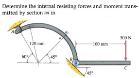
Determine the internal resisting forces and moment trans- mitted by section a in 500 N 120 mm 160 mm 60 45° 45


Q: Determine the internal resisting forces and moment trans- mitted by section aa in 1450 N 60° B 240…
A: Given data in form of figure is
Q: 03 m k= 200 N /m 04m
A: according to the given details in the question.
Q: The beam is loaded with a uniformly varying load 0 at point D and maximum of 7 kN/m at the fixed…
A: It is required to determine moment about fixed support
Q: Determine the nominal resisting moment capacity (Mn)for a W 27 × 94 for the following unbraced…
A: given: Determine the nominal resisting moment capacity (Mn)for a W 27 × 94 for the following…
Q: the bar element's linear shape, or interpolation ons are: N1= 1-x/L, and N2= x/L (where L is the ent…
A:
Q: The two bars, pinned together at B, are supported by a frictionless surface at A and built-in…
A: We have given, The two bars, pinned together at B, are supported by a friction less surface at A and…
Q: =M- 400x 0.15cos30-320x0.30 %3D 160 400 N mm = 148 Nm CCW cample : Replace the three forces acting…
A:
Q: The beam is subjected to applied loads as shown. Determine the moment at 12 ft from support A &…
A: It is required to determine moment at 12 ft from support A shear at 6 ft from right end E
Q: Determine the reaction moment at the fixed support A in N.m. Given that F=5N and L=3 m. Neglect the…
A: Let MA =Reaction moment at the fixed support A in counter clockwise directions F=5N L=3m Now we…
Q: Q3/ The member is subjected to a force of F = 6KN. I0 = 45', determine the moment produced by Fabout…
A:
Q: A beam is made from polypropylene plastic and has a stress–strain diagram that can be approximated…
A: Draw the stress plot of the cross-section.
Q: Determine the resultant internal bending moment acting on the cross section at point C in the beam…
A:
Q: Determine the reactive forces and moments at the point O and point A 6 kN/m 15 kN 500 kN m 7.5 m 4.5…
A:
Q: 1 A 150-N pull T is applied to a cord, which is wound securely around the inner hub of the drum.…
A: As per given Force =150 N r1=0.125m r2=0.2m We have determine moment T and angle
Q: 0.5 Qu Determine the moment Soo N of the fur ce system 0.5 wi th nespect shown to 1200 N 30 Point
A: In the given force system line of action of the force of 500 N coincide with the line of point o.…
Q: Replace the loads acting on the beam, as shown by a single resultant force R and find its location…
A:
Q: Determine the x-y and n-t components of the 39-kip force F acting on the simply-supported beam. F =…
A:
Q: Find the maximum moment of the beam loaded as shown. Express your final answer in N.m to the nearest…
A:
Q: Determine the reactions at A and B for the beam subjected to the distributed and concentrated loads.…
A:
Q: A force F of magnitude 76 N is applied to the gear. Determine the moment (positive if…
A:
Q: Determine the maximum moment (k-ft) at the given structure. Support A is fixed, joint B is a pin and…
A: Given: The structure is shown below:
Q: Show the Shear-Moment Diagram. (Use equation method) 5 kN kN W = 2 m A B 4m 3m C 3 m 4 kN D
A: Support reaction:
Q: Determine the internal moment in kip-ft at the distance 14 ft. from point A (it is the point between…
A:
Q: The bent bar is supported by smooth journal bearings at A, B and C and is subjected to couple moment…
A:
Q: ne the shear force Vin the beam at the point located 2 kN/m 3 m 4.70 kN 5 kN/m {]]]] 5 m 14.30 kN
A:
Q: 1.5 m 2 m HW06-2 Determine the angles 0 and o made between the axes OA of the flag pole and AB and…
A:
Q: Draw the free body diagram. 80 mg 60 20 650 mm 200 925 mm mm By
A: Solution: The free body diagram of the inclined beam is shown below:
Q: 3.The bending stress at a distance (h/2) of the I-section shown below is zero. (True/False) |21
A: Disclaimer: Since you have asked multiple questions, we will solve the first question for you. If…
Q: Determine the shear force V in the beam at the point located 4.50 m to the left of point C. The…
A: Given:To determine the shear force in the beam at 4.50m from C.Reaction at A, RA=65.6KNUDL, w=7.0…
Q: 15 kN 18 kN 40 kN/m A D 3 m 6 m 4 m FIGURE P7.19
A: Find the moment at 1.25 m left of C .
Q: Determine the internal resisting forces and moment trans- mitted by section aa in B 30 750 Ib 30 in.…
A: Given: The radius of curvature, R= 30 in force at the end, FP=750 lb at an angle 30o The radius of…
Q: A force F of magnitude 80 N is applied to the gear. Determine the moment (positive if…
A: Given:Force applied to the gear, F=80 NAngle at which force is applied, θ=17°radius of the gear,…
Q: Determine the moment of the force about point O. Neglect the thickness of the member. Assume F = 60…
A:
Q: Determine the resultant internal loadings on the cross section at point D. 1 m 2 m 1.25 kN/m DEB 15…
A:
Q: Q 3/AForce of 200 N in applied to the bar at anyle e= 45, Detormine the moment at point A in Figure…
A:
Q: Determine the internal resisting forces and moment trans- mitted by section aa in 24 70 B la 500 Ib.…
A: Draw the F.B.D of the bar ABC.
Q: Determine the reaction moment at the fixed support A in N.m. Given that F= 5 N and L=3 m. Neglect…
A: Force Force is a vector quantity which has direction and magnitude. Force is a change in momentum…
Q: Determine the internal resisting forces and moment trans- mitted by section aa in 3 kN 120 mm D 100…
A: Consider the free body diagram shown below for the member ABC.
Q: Draw the Shear force and Bending moment for th Following then determine the maximum momen and the…
A:
Q: 15.Form the Fig (2) The second moment of area I, is then given by: 50mm Imm 120mm 2mm Fig. (2) 2mm…
A: Given Data: Width of the top flange, w=50 mm
Q: The vertical bar is cantilevered to the floor as shown. Determine the moment of the loads at B. 800…
A: Given Data: The magnitude of force at outer end is F = 800 N. The lower magnitude of trapezium load…
Q: 8 kN/m 5 kN/m to 1.5 m -0.75 m 0.75 m What is the moment induced by this distributed load at O…
A:
Q: Determine the magnitude of moment (Nm) of the 681-N force about point A if x = 0.4 m , y = 0.68 m,…
A:
Q: Determine the x, y, z components of internal loading at a section passing through point B in the…
A: Given structure:
Q: Q1: Determine the moment of 50N force shown in Fig. about point O by at least ways? two 100 mm- 200…
A: We are suppose to solve only one question. Please post other question as a separate question.
Q: The metal stud punch is subjected to a force of 120 N on the handle. determine the magnitude of the…
A: Moment acting about point A FBCcos3050=120200+300FBC=1.39 kN Vertical forces…
Q: Determine the internal forces and bending moment at point C. Express these based on the sign…
A: To find: Internal forces at point C = ? internal bending moment at C = ?
Q: 2. In the design of an automotive control arm it is known that the spring force Fs =800N. Find the…
A: Now the force can be given as Fs→=fxi^+fyj^+fzk^Fx=Fssin 45°=800*sin 45°=207.05 i^Fy=0 j^Fzy=Fscos…

Step by step
Solved in 2 steps

- Determine the smallest allowable diameter of the shaft which is subjected to the concentrated forces. The journal bearing at A and B only support vertical forces. The allowable bending stress is σallow= 160 MPa Bearing A only receives forces in the radial direction of the bearing. Bearing B is a steering bearing and also carries longitudinal loads on the shaft. F1= 10kN F2=23 kN L1=420 mm L2= 310mm L3=540mmDetermine the equations to draw the shear force diagram and bending moment diagram. Consequently, drawthe shear force and bending moment diagram for the following load diagram. n=64The three-bar truss in Fig. a is subjected to a horizontal force of 5 kip. If the cross-sectional area of each member is 0.20 in2, determine the horizontal displacement at point B. E = 29(103) ksi.
- An A-36 steel strap having a thickness of 10 mm and a width of 20 mm is bent into a circular arc of radius r = 10 m. Determine the maximum bending stress in the strap.Determine the nominal resisting moment capacity in kip-feet for a W14 x 34 that has an unbraced span length of 15 feet. how do you find Mu =136Determine the internal normal force, shear force, and bending moment at points D and E of the bell crank that is pinned at A and supported by a short link BC.
- The stress–strain diagram for a titanium alloy can be approximated by the two straight lines. If a strut made of this material is subjected to bending, determine the moment resisted by the strut if the maximum stress reaches a value of (a) sA and (b) sB.Solve Prob. 10.54 assuming that A and B are connected by a spring of stiffness k = 0.3 W/b and free length b.Solve Prob. 7.29 if =0.
- Determine the bending strain energy in the 2-in.- diameter A-36 steel rod.The W24 * 104 A-36 steel beam is used to support the uniform distributed load and a concentrated force which is applied at its end. If the force acts at an angle with the vertical as shown, determine the horizontal and vertical displacement at A.Determine the normal force, shear force and moment at point E and F. Tabulate the final anwer in rounding upto 3 significant figures E F Normal Force (lb) Shear Force (lb) Moment (lb ft) Weight of Crate = 200 lb