determine the line-to-neutral (120 V)

Power System Analysis and Design (MindTap Course List)
6th Edition
ISBN:9781305632134
Author:J. Duncan Glover, Thomas Overbye, Mulukutla S. Sarma
Publisher:J. Duncan Glover, Thomas Overbye, Mulukutla S. Sarma
Chapter3: Power Transformers
Section: Chapter Questions
Problem 3.64P: The per-unit equivalent circuit of two transformers Ta and Tb connected in parallel, with the same...

Related questions

Question
Transcribed Image Text:Example 3.2
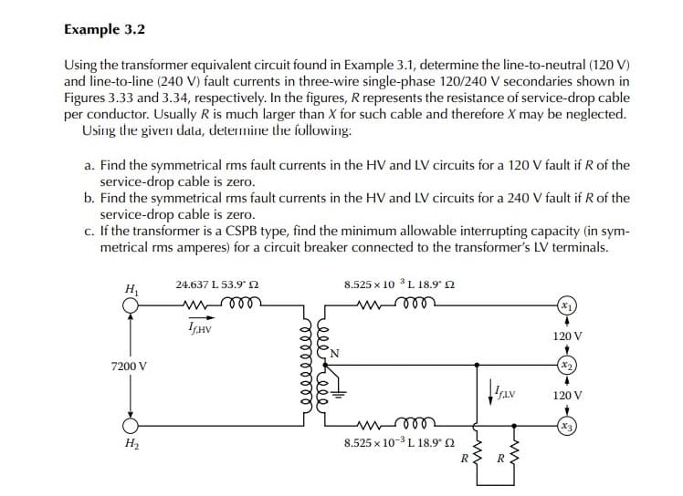
Using the transformer equivalent circuit found in Example 3.1, determine the line-to-neutral (120 V)
and line-to-line (240 V) fault currents in three-wire single-phase 120/240 V secondaries shown in
Figures 3.33 and 3.34, respectively. In the figures, R represents the resistance of service-drop cable
per conductor. Usually R is much larger than X for such cable and therefore X may be neglected.
Using the given dala, determine the following:
a. Find the symmetrical rms fault currents in the HV and LV circuits for a 120 V fault if R of the
service-drop cable is zero.
b. Find the symmetrical rms fault currents in the HV and LV circuits for a 240 V fault if R of the
service-drop cable is zero.
c. If the transformer is a CSPB type, find the minimum allowable interrupting capacity (in sym-
metrical rms amperes) for a circuit breaker connected to the transformer's LV terminals.
24.637 L 53.9 2
8.525 x 10 L 18.9 n
H
(x)
ISHV
120 V
7200 V
X2
120 V
x3
H2
8.525 x 10⁻³ L 18.9° 0
R> R
elehele
lelllllll
Expert Solution
This question has been solved!
Explore an expertly crafted, step-by-step solution for a thorough understanding of key concepts.

Step by step
Solved in 3 steps with 3 images

Knowledge Booster


Learn more about
Need a deep-dive on the concept behind this application? Look no further. Learn more about this topic, electrical-engineering and related others by exploring similar questions and additional content below.Recommended textbooks for you
Power System Analysis and Design (MindTap Course …
Electrical Engineering
ISBN:
9781305632134
Author:
J. Duncan Glover, Thomas Overbye, Mulukutla S. Sarma
Publisher:
Cengage Learning
Power System Analysis and Design (MindTap Course …
Electrical Engineering
ISBN:
9781305632134
Author:
J. Duncan Glover, Thomas Overbye, Mulukutla S. Sarma
Publisher:
Cengage Learning