Determine the magnitudes of the forces C and T shown in figure (1), which, along with the other three foroes shown, act on the bridgo-truss joint. |3+h kN 16 AN 16 AN 40 Fig.1. Q1
Determine the magnitudes of the forces C and T shown in figure (1), which, along with the other three foroes shown, act on the bridgo-truss joint. |3+h kN 16 AN 16 AN 40 Fig.1. Q1

International Edition---engineering Mechanics: Statics, 4th Edition
4th Edition
ISBN:9781305501607
Author:Andrew Pytel And Jaan Kiusalaas
Publisher:Andrew Pytel And Jaan Kiusalaas
Chapter6: Beams And Cables
Section: Chapter Questions
Problem 6.15P: The structure is supported by a pin at C and a cable attached to A. The cable runs over the small...

Related questions
Question
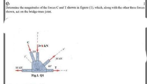
Transcribed Image Text:Determine the magnitudes of the forces C and T shown in figure (1), which, along with the other three forces
shown, act on the bridge-truss joint.
|3+h kN
16 kN
16 kN
Fig.1. Q1
Expert Solution
This question has been solved!
Explore an expertly crafted, step-by-step solution for a thorough understanding of key concepts.

Step by step
Solved in 2 steps with 2 images

Recommended textbooks for you
International Edition---engineering Mechanics: St…
Mechanical Engineering
ISBN:
9781305501607
Author:
Andrew Pytel And Jaan Kiusalaas
Publisher:
CENGAGE L
International Edition---engineering Mechanics: St…
Mechanical Engineering
ISBN:
9781305501607
Author:
Andrew Pytel And Jaan Kiusalaas
Publisher:
CENGAGE L