Design and simulate the circuit in figure 2 using Multisim software and get the following parameters Current in circuit I =…………………………mA Voltage across R1 ER =…………………………V Voltage across L1 EL =…………………………V Power dissipated P =…………………………mW


Design and simulate the circuit in figure 2 using Multisim software and get the following parameters
Current in circuit I =…………………………mA
Voltage across R1 ER =…………………………V
Voltage across L1 EL =…………………………V
Power dissipated P =…………………………mW

Step by step
Solved in 3 steps with 2 images

Draw power triangle and phasor diagram of the circuit
Compare the values measured in software analysis and calculated in mathematical
analysis and discuss the result obtained
Calculate the following values using circuit analysis with detailed steps of calculation.
Reactance of L1 XL = …………..Ω
Total Impedance ZT = …………..Ω
Current in circuit I =……………mA
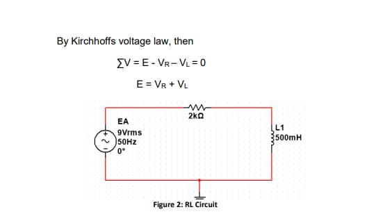
Figure 2: RL Circuit
Voltage across R1 ER =……………V
Voltage across L1 EL =……………V
Power dissipated P =……………W
Quality Factor Q.F = XL /R =………
Phase angle θ =……………
Total reactive power in the circuit Q =……………VAr
Apparent power delivered by source S =…………….VA
Observe the following waveforms using oscilloscope
Source voltage and source current waveforms
Voltage across resistor
Voltage across inductor


