draw the output voltage and current waveforms


Q: The intrinsic carrier concentration for Si is 1010/cm3. If 1014 donor atoms/cm3 is added, then find ...
A: According to the law of mass action for semiconductors, the following relation can be written: n0×p0...
Q: Once a thyristor begins to conduct, what condition(s) is necessary to cease conduction?
A:
Q: walue of ſ D. dS is equal to
A:
Q: 15. What is the relationship of the gate pulses to the two thyristors in a full-wave ac phase contro...
A: In 1∅ full wave two thyristor, for continuous conduction, each thyristor should be on for one half c...
Q: Briefly describe the effects the switching control signal frequency has on the output voltage and cu...
A: We’ll answer the first question since the exact one wasn’t specified. Please submit a new question s...
Q: 1. Find the value of vo using the superposition principle. Check your answer using the method of you...
A: To solve by using the superposition principle,first consider the only the current source and short c...
Q: On the output characteristic curve of a JFET for VGS = 0, the pinch-off voltage is- %3D Select one: ...
A: On the output characteristic curve of a JFET for VGS = 0, The pinch-off voltage is between the ohmic...
Q: Redraw the circuit with a four-terminalNMOS transistor with its body connected to −5 V
A: The circuit diagram is given as,
Q: Three lossless lines are connected as shown in the figure below. Determine the input impedance. 2/2 ...
A: The equivalent impedance between the load and the impedance, Z03 is determined as: Z3=VlII=Z03ZL+jZ0...
Q: Find ia
A: Redrawing the circuit diagram:
Q: The current flowing through a 2-H inductance is given by 5 exp( −20t ) A. Find expressions for the v...
A: Given data, The value of inductor L = 2 H. The value of current i(t) = 5exp(-20t) A. The expressio...
Q: The emf induced in the dc generator armature winding is * O AC and DC O DC O None of the above O AC
A:
Q: For the network of Fig. 3: i) Determine Zi and Z0. ii) Calculate Av
A: From the given configuration: VCC=20 Vβ=140RE=1.2 kΩRB=390 kΩRC=2.2 kΩro=100 kΩ The base current i...
Q: A circuit with three parameters connected in series R= 5 ohm,XL=j2 ohm and Z the St=36.4 volt ampere...
A:
Q: If the RMS signal strength received from a base station is -89 dBm, and we are travelling at 30 kilo...
A: Given: RMS signal received from the base station is -89 dBm. Fade is defined as any signal below -95...
Q: Which motor cannot be started on no load none of the above O shunt motors O series motors O cumulati...
A: Given: The motor cannot be started on no load is determined as, None of the above Shunt motors Seri...
Q: Type your quastion here
A: Acoording to the given data : p=6 Pload=12000 W V=240 V Eg1=250 V ϕ2=1.2ϕ1 Number of parallel paths ...
Q: Shunt generator running at 1500 rpm, if flux is reduced by half, then what is the new speed 1500 r.p...
A:
Q: Design a lag compensator so that the system of Figure 1, where G(3) = K(s+4) (s+2)(s+6)(s+8)
A: A lag compensator is designed to generate steady state sinusoidal signal having a phase lag with app...
Q: Determine vo for each network of Fig. 2.155 for the input shown.
A:
Q: A balanced wye-connected three-phase source has line-to-neutral voltages of 240 V rms. Find the rms ...
A: Given data, The value of phase rms voltage VPrms = 240 V. The value of resistance R1 = 10 Ω The val...
Q: At start the d.c motor draw armature current is times more than the full load current 15 to 20 2 to ...
A: For a dc motor, the armature current is given as Ia=V-E/Ra Here, E is the induced back emf. V is th...
Q: What is the output voltage of the circuit shown if R = 20 k , C = 0.02 F,and vi = 2.5 sin 2000πt V?
A: Given data, The value of resistance R = 20 k. The value of capacitor C = 0.02 F. The value of input...
Q: Give me detailed solutions with explanations.
A: For question 4: Following steps to be followed for solving: Firstly mark positions of switch as (A)...
Q: For the network of Fig. 1: i) Draw the re model equivalent circuit. ii) Calculate IB, IC, and re. ii...
A: To draw the re model equivalent circuit as shown below,
Q: This questions from electronics two course
A:
Q: In a common-source amplifier circuit. The output voltage at the lower cutoff frequency is 8 mV. The ...
A: Given values, output voltage at lower frequency is 8 mV
Q: Q4/A 25 KVA transformer supplies a load of 12 KW at a power factor of 0.6 lagging. If additional uni...
A:
Q: (a) Draw the AC equivalent circuit for the circuit given in Fig. 4.(b) Calculate the overall/total v...
A:
Q: Explain why the maximum value of the duty cycle must be limited in certain boost choppers. //(L-7)
A: We know that the boost chopper output (EO) is proportional to the DC voltage provided that the boost...
Q: What effect does increasing rotor circuit resistance have on the breakdown torque and on slip at whi...
A: According to the maximum breakdown torque:
Q: :The armature of a dc machine is laminated to reduce Eddy current loss O copper losses friction and ...
A: When lamination is done on armature of the dc machine it minimizes the cross sectional area of windi...
Q: 1. a) Find an expression for the equivalent resistance of two resistorsof value R in series.2. b) Fi...
A: As per our policy, i have attempted 3 parts. a) Calculating equivalent resistance of two resistor in...
Q: (a) Determine the Fourier-transform transfer function (frequency-response function) of the electrica...
A: A: The equivalent circuit in frequency for RL circuit is shown below: To calculate V2(s), apply vol...
Q: What is the peak output voltage of a three phase three pulse rectifier operating on a line to line v...
A:
Q: A single-phase load is supplied by a single-phase voltage source. If the current flowing from the lo...
A:
Q: An amplifier has an open-circuit transresistance gain of 200 Ω, a short-circuit transconductance gai...
A: The current gain of the amplifier is the ratio of the output current (Iop) to the input current (Iin...
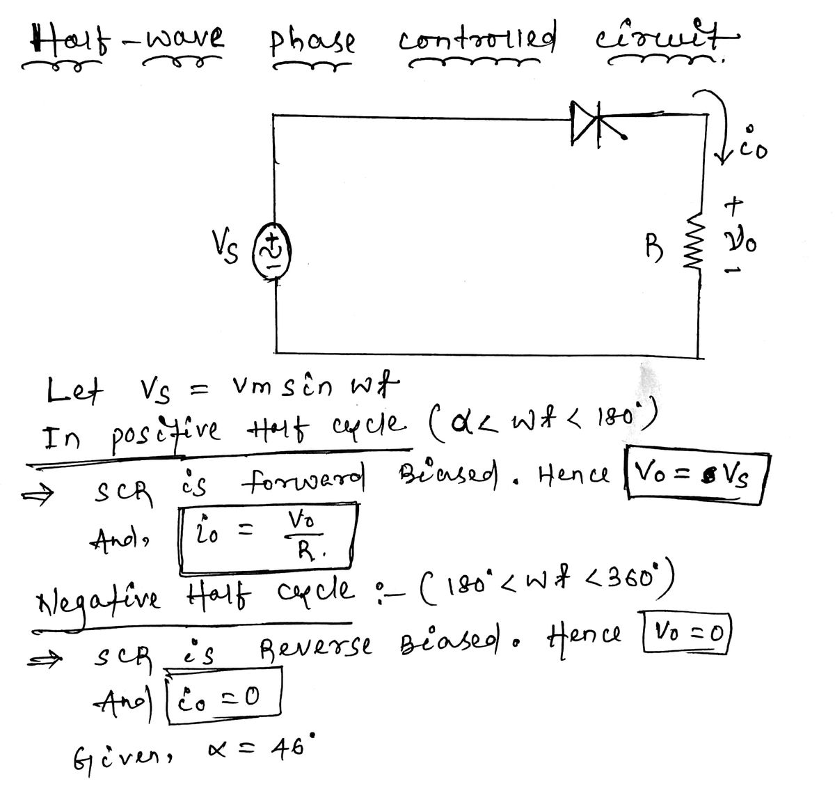
For a half-wave phase control circuit draw the output voltage and current waveforms when firing angle α = 46°. Consider the load to be resistive.

Step by step
Solved in 2 steps with 2 images


- For a full-wave phase control circuit draw the output voltage and current waveforms when firing angle α = 38° and consider the load to be inductive? also, For a half-wave phase control circuit draw the output voltage and current waveforms when firing angle α = 46° Consider the load to be resistive.A single phase full converter feeds power to RLE load with R=10 ohm, L=10 mH and E=50 V, the ac source voltage is 230 V, 50 Hz. For continuous conduction, what is the average value of load current for firing angle delay of 600 ?I am getting the output of the clamper circuit wrong, how will this circuit be output ? circuit question : Set the input voltage signal to a sinusoid with 100 Hz frequency and 20V peak-to-peak amplitude with C=1μF. Obtain and plot the input and output voltage waveforms.
- write the procedure to design phase lead compensatorDraw the schematic of the Unidirectional Full Wave Control and its load voltage waveform.A 3-phase half wave controlled AC to DC converter is supplied from a 250V, supply. Assume the thyristor voltage drop to be 1.6V and the load current to be continuous. Evaluate the mean output voltage when firing angle is varied at 45(degree) , 60(degree) and 90(degree)
- If the no-load output voltage of a regulator is 24.8V and the full-load output is 23.9V, what is the load regulation expressed as a percentage?Draw the circuit diagram of a Transformer Coupled Push Pull Amplifier. Explain its working taking a sinusoidal signal as the input.For the C.R.O. square voltage waveform shown in Figure determine (a) the periodic time, (b) the frequency and (c) the peak-to-peak voltage. The 'time/cm' (or timebase control) switch is on 100 us/cm and the 'volts/cm' (or signal amplitude control) switch is on 20V/cm.
- Draw the schematic of the Bidirectional Full Wave Control and its load voltage waveform.Derive the average and rms values of output voltages and currents for three phase semi converter. Power Electronicsa) Demonstrate input and output waveform of single phase Cyclo-converter such that output frequency is 1/3 of input supply frequency with circuit diagram. b) Perform the calculation to analyze (i) output RMS voltage and (ii) input power factor of single-phase AC voltage controller as shown in the following figure. Suppose converter has a resistive load of R=‘A’ Ohm and the input voltage is Vs=220, 50Hz with a delay angle of π/3. A= 4