Draw the physical diagram of the beam%; (i). Draw the free body diagram of the beam; (iii). Estimate the reaction forces at the support; (iv). Draw shear force and bending moment diagrams for the given values and identify maximum shear force and maximum bending moment; (v). Identify the support with maximum reaction


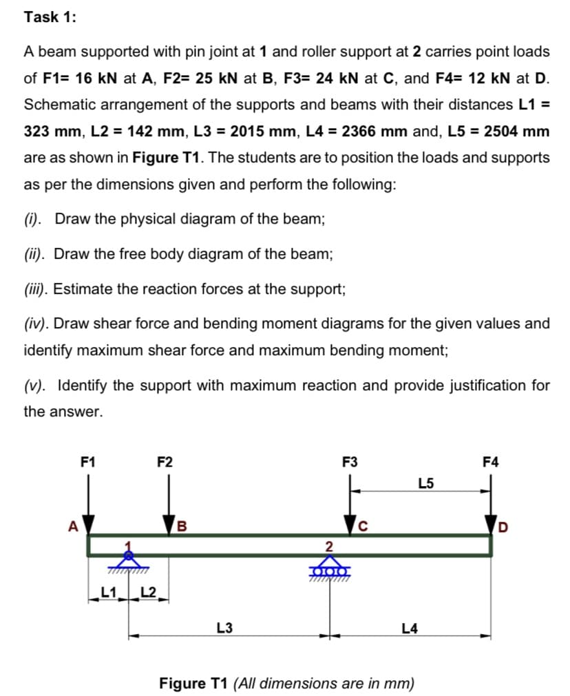
A beam supported with pin joint at 1 and roller support at 2 carries point loads of F1= 16 kN at A, F2= 25 kN at B, F3= 24 kN at C, and F4= 12 kN at D. Schematic arangement of the supports and beams with their distances L1 = 323 mm, L2 = 142 mm, L3 = 2015 mm, L4 = 2366 mm and, L5 =2504 mm are as shown in Figure T1. The students are to position the loads and supports as per the dimensions given and perform the following:
(i). Draw the physical diagram of the beam%;
(i). Draw the free body diagram of the beam;
(iii). Estimate the reaction forces at the
support;
(iv). Draw shear force and bending moment diagrams for the given values and identify maximum shear force and maximum bending moment;
(v). Identify the support with maximum reaction and provide justification for the answer.


Trending now
This is a popular solution!

Step by step
Solved in 2 steps with 4 images


