ds Shown belów, derive the equivalent resistance, Req. R1 R4 R5 R9 R12 100 100 100 100 100 Req R2 200 R15 202 R7 200 ... R10 200 R13 ... 200 R3 R6 R8 R11 R14 300 300 300 300 300
ds Shown belów, derive the equivalent resistance, Req. R1 R4 R5 R9 R12 100 100 100 100 100 Req R2 200 R15 202 R7 200 ... R10 200 R13 ... 200 R3 R6 R8 R11 R14 300 300 300 300 300

Delmar's Standard Textbook Of Electricity
7th Edition
ISBN:9781337900348
Author:Stephen L. Herman
Publisher:Stephen L. Herman
Chapter7: Parallel Circuits
Section: Chapter Questions
Problem 3PP: Using the rules for parallel circuits and Ohmslaw, solve for the missing values....

Related questions

Question
100%
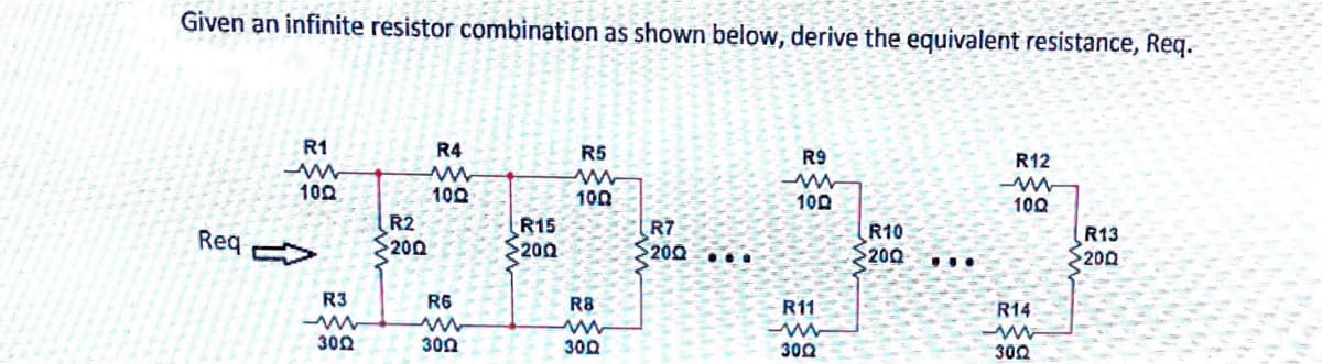
Transcribed Image Text:Given an infinite resistor combination as shown below, derive the equivalent resistance, Req.
R1
R4
R5
R9
R12
100
100
100
100
100
Req
R2
200
R15
200
R7
$200 ...
R10
$200
R13
200
...
R3
R6
R8
R11
R14
300
300
300
300
302
Expert Solution
This question has been solved!
Explore an expertly crafted, step-by-step solution for a thorough understanding of key concepts.

Step by step
Solved in 2 steps with 2 images

Knowledge Booster


Learn more about
Need a deep-dive on the concept behind this application? Look no further. Learn more about this topic, electrical-engineering and related others by exploring similar questions and additional content below.Recommended textbooks for you
Delmar's Standard Textbook Of Electricity
Electrical Engineering
ISBN:
9781337900348
Author:
Stephen L. Herman
Publisher:
Cengage Learning
Delmar's Standard Textbook Of Electricity
Electrical Engineering
ISBN:
9781337900348
Author:
Stephen L. Herman
Publisher:
Cengage Learning