(e) Determine the impulse response function h(t) for this filter. (f) Hence, or otherwise, determine the output vout(t) for a rectangular pulse input Vin (1) = vorect(t/T) (g) Sketch the form of vout(t) with the values vo = 5 V and r = 5.0 us, inserting appropriate values on the time and voltage axes. !!
(e) Determine the impulse response function h(t) for this filter. (f) Hence, or otherwise, determine the output vout(t) for a rectangular pulse input Vin (1) = vorect(t/T) (g) Sketch the form of vout(t) with the values vo = 5 V and r = 5.0 us, inserting appropriate values on the time and voltage axes. !!

Introductory Circuit Analysis (13th Edition)
13th Edition
ISBN:9780133923605
Author:Robert L. Boylestad
Publisher:Robert L. Boylestad
Chapter1: Introduction
Section: Chapter Questions
Problem 1P: Visit your local library (at school or home) and describe the extent to which it provides literature...

Related questions
Question
Do e) f) and g) ?
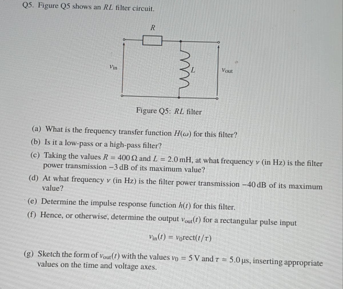
Transcribed Image Text:Q5. Figure Q5 shows an RL filter circuit.
Vin
Vout
Figure Q5: RL filter
(a) What is the frequency transfer function H(@) for this filter?
(b) Is it a low-pass or a high-pass filter?
(c) Taking the values R = 400 2 and L = 2.0 mH, at what frequency v (in Hz) is the filter
power transmission -3 dB of its maximum value?
(d) At what frequency v (in Hz) is the filter power transmission –40 dB of its maximum
value?
(e) Determine the impulse response function h(t) for this filter.
(f) Hence, or otherwise, determine the output Vout(t) for a rectangular pulse input
Vin (1) = vorect(t/T)
(g) Sketch the form of vout (t) with the values vo = 5 V and r = 5.0 us, inserting appropriate
values on the time and voltage axes.
Expert Solution
This question has been solved!
Explore an expertly crafted, step-by-step solution for a thorough understanding of key concepts.

Step by step
Solved in 3 steps with 3 images

Knowledge Booster


Learn more about
Need a deep-dive on the concept behind this application? Look no further. Learn more about this topic, electrical-engineering and related others by exploring similar questions and additional content below.Recommended textbooks for you
Introductory Circuit Analysis (13th Edition)
Electrical Engineering
ISBN:
9780133923605
Author:
Robert L. Boylestad
Publisher:
PEARSON

Delmar's Standard Textbook Of Electricity
Electrical Engineering
ISBN:
9781337900348
Author:
Stephen L. Herman
Publisher:
Cengage Learning

Programmable Logic Controllers
Electrical Engineering
ISBN:
9780073373843
Author:
Frank D. Petruzella
Publisher:
McGraw-Hill Education
Introductory Circuit Analysis (13th Edition)
Electrical Engineering
ISBN:
9780133923605
Author:
Robert L. Boylestad
Publisher:
PEARSON
Delmar's Standard Textbook Of Electricity
Electrical Engineering
ISBN:
9781337900348
Author:
Stephen L. Herman
Publisher:
Cengage Learning
Programmable Logic Controllers
Electrical Engineering
ISBN:
9780073373843
Author:
Frank D. Petruzella
Publisher:
McGraw-Hill Education

Fundamentals of Electric Circuits
Electrical Engineering
ISBN:
9780078028229
Author:
Charles K Alexander, Matthew Sadiku
Publisher:
McGraw-Hill Education

Electric Circuits. (11th Edition)
Electrical Engineering
ISBN:
9780134746968
Author:
James W. Nilsson, Susan Riedel
Publisher:
PEARSON

Engineering Electromagnetics
Electrical Engineering
ISBN:
9780078028151
Author:
Hayt, William H. (william Hart), Jr, BUCK, John A.
Publisher:
Mcgraw-hill Education,