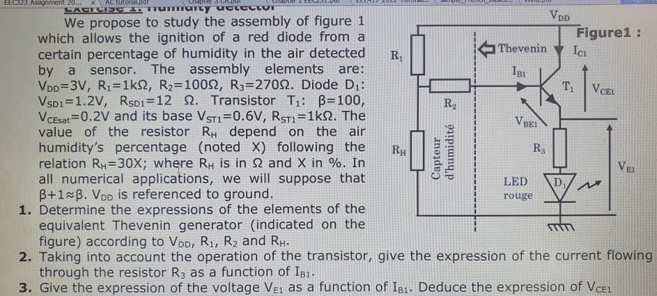
EEC323 Assignment 20... x AC tutorial.par Chapter 3 CA.pur LACICISE 1. mummarty uctector Limpter 1 CEL 201 We propose to study the assembly of figure 1 which allows the ignition of a red diode from a certain percentage of humidity in the air detected by a sensor. The assembly elements are: VDD=3V, R₁=1km2, R₂=10092, R3=27022. Diode D₁: VSD1 1.2V, RSD1=12 2. Transistor T₁: B=100, VCEsat 0.2V and its base VST1=0.6V, RST1=1k2. The value of the resistor RH depend on the air humidity's percentage (noted X) following the relation RH=30X; where RH is in 2 and X in %. In R₁ JAUTRINAE RH R₂ Capteur d'humidité Wiktor *varmapur Thevenin IBI VBEI R3 VDD LED rouge Figure1: Ici T₁ VCEL all numerical applications, we will suppose that B+1 B. VDD is referenced to ground. 1. Determine the expressions of the elements of the equivalent Thevenin generator (indicated on the figure) according to VDD, R₁, R₂ and RH. 2. Taking into account the operation of the transistor, give the expression of the current flowing through the resistor R3 as a function of IB1. 3. Give the expression of the voltage VEL as a function of IB1. Deduce the expression of VCE1 VEL D₁ M
EEC323 Assignment 20... x AC tutorial.par Chapter 3 CA.pur LACICISE 1. mummarty uctector Limpter 1 CEL 201 We propose to study the assembly of figure 1 which allows the ignition of a red diode from a certain percentage of humidity in the air detected by a sensor. The assembly elements are: VDD=3V, R₁=1km2, R₂=10092, R3=27022. Diode D₁: VSD1 1.2V, RSD1=12 2. Transistor T₁: B=100, VCEsat 0.2V and its base VST1=0.6V, RST1=1k2. The value of the resistor RH depend on the air humidity's percentage (noted X) following the relation RH=30X; where RH is in 2 and X in %. In R₁ JAUTRINAE RH R₂ Capteur d'humidité Wiktor *varmapur Thevenin IBI VBEI R3 VDD LED rouge Figure1: Ici T₁ VCEL all numerical applications, we will suppose that B+1 B. VDD is referenced to ground. 1. Determine the expressions of the elements of the equivalent Thevenin generator (indicated on the figure) according to VDD, R₁, R₂ and RH. 2. Taking into account the operation of the transistor, give the expression of the current flowing through the resistor R3 as a function of IB1. 3. Give the expression of the voltage VEL as a function of IB1. Deduce the expression of VCE1 VEL D₁ M

Chapter59: Motor Startup And Troubleshooting Basics
Section: Chapter Questions
Problem 12SQ: How is a solid-state diode tested? Explain.

Related questions

Question
question 3 please
1 and 2 has been solved
Transcribed Image Text:EEC323 Assignment 20...
AC tutorial.par
сперс
LATENC
Tummarcy uctector
We propose to study the assembly of figure 1
which allows the ignition of a red diode from a
certain percentage of humidity in the air detected
by a sensor. The assembly elements are:
VDD=3V, R₁=1ks, R₂=10092, R3=27002. Diode D₁:
VSD1=1.2V, RSD1=12 . Transistor T₁: B=100,
VCEsat=0.2V and its base VST1=0.6V, RST1=1kQ2. The
value of the resistor RH depend on the air
humidity's percentage (noted X) following the
relation RH=30X; where RH is in 2 and X in %. In
all numerical applications, we will suppose that
3+1 B. VDD is referenced to ground.
1. Determine the expressions of the elements of the
equivalent Thevenin generator (indicated on the
figure) according to VDD, R₁, R₂ and RH.
2. Taking into account the operation of the transistor, give the expression of the current flowing
through the resistor R3 as a function of IB1.
3. Give the expression of the voltage VE1 as a function of IB1. Deduce the expression of VCE1
R₁
RH
R₂
Capteur
d'humidité 2
Thevenin
IBI
VB
BEI
R3
LED
rouge
VDD
Figure1:
ICI
T₁
D₁
VCEL
M
VEL
Expert Solution
This question has been solved!
Explore an expertly crafted, step-by-step solution for a thorough understanding of key concepts.

Step by step
Solved in 2 steps with 1 images

Knowledge Booster


Learn more about
Need a deep-dive on the concept behind this application? Look no further. Learn more about this topic, electrical-engineering and related others by exploring similar questions and additional content below.Recommended textbooks for you

Delmar's Standard Textbook Of Electricity
Electrical Engineering
ISBN:
9781337900348
Author:
Stephen L. Herman
Publisher:
Cengage Learning
Delmar's Standard Textbook Of Electricity
Electrical Engineering
ISBN:
9781337900348
Author:
Stephen L. Herman
Publisher:
Cengage Learning