EIRP Calculations 8) Consider a wireless transmitter that has an antenna gain of 5 dBi. Calculate the EIRP when the power fed to the antenna is 27 dBm. Ignore losses in the wire connecting the transmitter to the antenna.
EIRP Calculations 8) Consider a wireless transmitter that has an antenna gain of 5 dBi. Calculate the EIRP when the power fed to the antenna is 27 dBm. Ignore losses in the wire connecting the transmitter to the antenna.

Introductory Circuit Analysis (13th Edition)
13th Edition
ISBN:9780133923605
Author:Robert L. Boylestad
Publisher:Robert L. Boylestad
Chapter1: Introduction
Section: Chapter Questions
Problem 1P: Visit your local library (at school or home) and describe the extent to which it provides literature...

Related questions

Question
Solve and show work on paper reference is included
Transcribed Image Text:EIRP Calculations
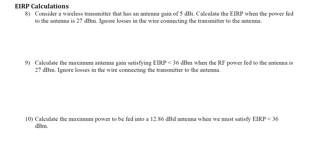
8) Consider a wireless transmitter that has an antenna gain of 5 dBi. Calculate the EIRP when the power fed
to the antenna is 27 dBm. Ignore losses in the wire connecting the transmitter to the antenna.
9) Calculate the maximum antenna gain satisfying EIRP < 36 dBm when the RF power fed to the antenna is
27 dBm. Ignore losses in the wire connecting the transmitter to the antenna.
10) Calculate the maximum power to be fed into a 12.86 dBd antenna when we must satisfy EIRP < 36
dBm.
![Loss Budgeting Handout
Simple Loss Budget Model
The simple loss budget model considers the channel
loss only as a single aggregated quantity. The channel loss
includes all possible components (e.g., wires, antennas, air)
between the transmitter and receiver.
SIMPLE LOSS BUDGET MODEL (all power values here in dB)
30-
20-
30-
0-
-30-
-20-
-30-
40-
-50 M
-60-
The receiver sensitivity is the minimum received power
for proper operation of the receiver. Received power below
this value results in unacceptably high Bit Error Rates
(BER). The difference between the actual received power
PRx and the receiver sensitivity Pax min is called the system
margin M. When M > 0 the system can operate properly,
with acceptable BER, and system can withstand a
temporary additional loss of M dB. In case M = 0, the
system is able to operate with acceptable BER, but there is no
margin for temporary additional channel loss. When M < 0, the
system cannot operate with acceptably low BER.
Wireless Loss Budget Model
The wireless loss budget model considers the various
contributions to the channel loss separately. The channel loss
Lch is here considered to be made up of (1) losses due to
antenna wires (LTx and LRx), (2) the air loss (Lair), and is
partially offset by (3) gains due to antennas (GTX and GRX)-
Antenna gain offsets the channel loss because, when set up
properly, real antennas concentrate more power towards the
receiving antenna more than an (ideal) isotropic antenna.
Loss budget with noise floor and SNR:
Proper system operation requires not only a minimum received power (the receiver sensitivity), but also a
minimum signal-to-noise ratio, SNR. The SNR is the ratio of the received power (in mW) to the RF power in
the noise floor (in mW), where RF noise floor Pnoise is essentially a random mixture of RF signals due to a
wide variety of RF sources. In decibel units the SNR is given by SNRAB = PRx_dBm - Pnoise_dBm-
Antenna Gain relative to isotropic (dBi units)
An isotropic antenna is an antenna that radiates equally in all directions of 3D space. No isotropic antenna
exists in the real world. The antenna gain G accounts for the fact that real antennas, instead of radiating
equally in all directions in 3D space, instead concentrate power in certain directions. The simplest case of a
real antenna is a dipole (a straight wire), which sends the strongest signal centered on and perpendicular to
the antenna's axis. The dipole radiates less in directions not perpendicular to its axis, radiating nothing along
its axis. Antenna gain is usually measured in units of dBi ("decibels relative to isotropic"),
giving the increase in received power over the case where the same transmitter power was
fed to an ideal isotropic antenna. The dipole antenna has a gain of 2.15 dBi.
Pr, feeds actual antenna
-70-
-30
La
dB
30
PT
10-
0-
PRI
-10-
PRs.in
WIRELESS LOSS BUDGET MODEL (all power values here in dB)
GR
Case of
general
GTX
20-PTX
Lich
Tx
Lich
PTX
Receiver sensitivity = minimum power
needed at R₂ = PRx, min
PRx ≥PRx, min →M>0, BER OK
PRx <PRx, min → BER high
PRK
-20-
-30- M
40- PRs. min
M = system margin = PRx - PRx, min
= Leh, max - Leh
Rx
PRX = PTX - Lich
Effective Isotropic Radiated Power (EIRP):
The EIRP is the power that an (ideal, non-existent) isotropic antenna would need to be fed
to result in the same power that the receiver antenna sees with the actual transmitting
antenna. If we include the loss of the wire between the transmitter and the antenna, then
Prx - Lwire is the amount of power reaching the antenna. The EIRP adjusts for the fact
that the actual transmitter antenna concentrates more power towards the receiver than an
isotropic antenna would and is given by EIRPaB = Prx.am-Lwire_dB + GTx_aBi-
Note that the EIRP is a characteristic of the transmission system only, and does NOT
depend on the receiver or receiving antenna gain.
Antenna gain relative to the dipole (dBd units)
The antenna gain can be measured either relative to the ideal isotropic antenna, in which
case the units on gain are dBi, or relative to a real dipole antenna, in which case the units
on gain are dBd ("decibels relative to dipole"). When oriented properly so the strongest
part of the signal aims at the receiver (always our assumption) the dipole antenna has a
gain of 2.15 dB. Thus we have GaBd = Gabi - 2.15 dB.
Lain
P. feeds
isotropic
antennal
LTX
Tx PTX
Leh LTx - GTx + Lair − GRx + LRx
M = PRx - PRx.min
Dipole gain
antenna gain
(in units of
[dBi])
LRX
RxPx = PTx-Lch
Isotropic gain
dB
30
10-
0-
-10-
-20-
-30-
-40
-60
-70-
-80
Lich
M
Ga
PTX
G[dBi)-G[did] +2.15 dB
PR
SNR SNR
PRs.i
EIRPau = Prxdum − Lwire_du + Grx_dB
Pie
EIRP feeds
isotropic
antenna
G[dBd]
G[dB]
2.15 dB
Higher antenna gain](/v2/_next/image?url=https%3A%2F%2Fcontent.bartleby.com%2Fqna-images%2Fquestion%2Fe922e3ce-608a-4bd4-be41-99612003611a%2Fff623dc6-31ac-49ee-953f-77d098e68efe%2F6590wg_processed.png&w=3840&q=75)
Transcribed Image Text:Loss Budgeting Handout
Simple Loss Budget Model
The simple loss budget model considers the channel
loss only as a single aggregated quantity. The channel loss
includes all possible components (e.g., wires, antennas, air)
between the transmitter and receiver.
SIMPLE LOSS BUDGET MODEL (all power values here in dB)
30-
20-
30-
0-
-30-
-20-
-30-
40-
-50 M
-60-
The receiver sensitivity is the minimum received power
for proper operation of the receiver. Received power below
this value results in unacceptably high Bit Error Rates
(BER). The difference between the actual received power
PRx and the receiver sensitivity Pax min is called the system
margin M. When M > 0 the system can operate properly,
with acceptable BER, and system can withstand a
temporary additional loss of M dB. In case M = 0, the
system is able to operate with acceptable BER, but there is no
margin for temporary additional channel loss. When M < 0, the
system cannot operate with acceptably low BER.
Wireless Loss Budget Model
The wireless loss budget model considers the various
contributions to the channel loss separately. The channel loss
Lch is here considered to be made up of (1) losses due to
antenna wires (LTx and LRx), (2) the air loss (Lair), and is
partially offset by (3) gains due to antennas (GTX and GRX)-
Antenna gain offsets the channel loss because, when set up
properly, real antennas concentrate more power towards the
receiving antenna more than an (ideal) isotropic antenna.
Loss budget with noise floor and SNR:
Proper system operation requires not only a minimum received power (the receiver sensitivity), but also a
minimum signal-to-noise ratio, SNR. The SNR is the ratio of the received power (in mW) to the RF power in
the noise floor (in mW), where RF noise floor Pnoise is essentially a random mixture of RF signals due to a
wide variety of RF sources. In decibel units the SNR is given by SNRAB = PRx_dBm - Pnoise_dBm-
Antenna Gain relative to isotropic (dBi units)
An isotropic antenna is an antenna that radiates equally in all directions of 3D space. No isotropic antenna
exists in the real world. The antenna gain G accounts for the fact that real antennas, instead of radiating
equally in all directions in 3D space, instead concentrate power in certain directions. The simplest case of a
real antenna is a dipole (a straight wire), which sends the strongest signal centered on and perpendicular to
the antenna's axis. The dipole radiates less in directions not perpendicular to its axis, radiating nothing along
its axis. Antenna gain is usually measured in units of dBi ("decibels relative to isotropic"),
giving the increase in received power over the case where the same transmitter power was
fed to an ideal isotropic antenna. The dipole antenna has a gain of 2.15 dBi.
Pr, feeds actual antenna
-70-
-30
La
dB
30
PT
10-
0-
PRI
-10-
PRs.in
WIRELESS LOSS BUDGET MODEL (all power values here in dB)
GR
Case of
general
GTX
20-PTX
Lich
Tx
Lich
PTX
Receiver sensitivity = minimum power
needed at R₂ = PRx, min
PRx ≥PRx, min →M>0, BER OK
PRx <PRx, min → BER high
PRK
-20-
-30- M
40- PRs. min
M = system margin = PRx - PRx, min
= Leh, max - Leh
Rx
PRX = PTX - Lich
Effective Isotropic Radiated Power (EIRP):
The EIRP is the power that an (ideal, non-existent) isotropic antenna would need to be fed
to result in the same power that the receiver antenna sees with the actual transmitting
antenna. If we include the loss of the wire between the transmitter and the antenna, then
Prx - Lwire is the amount of power reaching the antenna. The EIRP adjusts for the fact
that the actual transmitter antenna concentrates more power towards the receiver than an
isotropic antenna would and is given by EIRPaB = Prx.am-Lwire_dB + GTx_aBi-
Note that the EIRP is a characteristic of the transmission system only, and does NOT
depend on the receiver or receiving antenna gain.
Antenna gain relative to the dipole (dBd units)
The antenna gain can be measured either relative to the ideal isotropic antenna, in which
case the units on gain are dBi, or relative to a real dipole antenna, in which case the units
on gain are dBd ("decibels relative to dipole"). When oriented properly so the strongest
part of the signal aims at the receiver (always our assumption) the dipole antenna has a
gain of 2.15 dB. Thus we have GaBd = Gabi - 2.15 dB.
Lain
P. feeds
isotropic
antennal
LTX
Tx PTX
Leh LTx - GTx + Lair − GRx + LRx
M = PRx - PRx.min
Dipole gain
antenna gain
(in units of
[dBi])
LRX
RxPx = PTx-Lch
Isotropic gain
dB
30
10-
0-
-10-
-20-
-30-
-40
-60
-70-
-80
Lich
M
Ga
PTX
G[dBi)-G[did] +2.15 dB
PR
SNR SNR
PRs.i
EIRPau = Prxdum − Lwire_du + Grx_dB
Pie
EIRP feeds
isotropic
antenna
G[dBd]
G[dB]
2.15 dB
Higher antenna gain
Expert Solution
This question has been solved!
Explore an expertly crafted, step-by-step solution for a thorough understanding of key concepts.

Step by step
Solved in 3 steps

Knowledge Booster


Learn more about
Need a deep-dive on the concept behind this application? Look no further. Learn more about this topic, electrical-engineering and related others by exploring similar questions and additional content below.Recommended textbooks for you
Introductory Circuit Analysis (13th Edition)
Electrical Engineering
ISBN:
9780133923605
Author:
Robert L. Boylestad
Publisher:
PEARSON

Delmar's Standard Textbook Of Electricity
Electrical Engineering
ISBN:
9781337900348
Author:
Stephen L. Herman
Publisher:
Cengage Learning

Programmable Logic Controllers
Electrical Engineering
ISBN:
9780073373843
Author:
Frank D. Petruzella
Publisher:
McGraw-Hill Education
Introductory Circuit Analysis (13th Edition)
Electrical Engineering
ISBN:
9780133923605
Author:
Robert L. Boylestad
Publisher:
PEARSON
Delmar's Standard Textbook Of Electricity
Electrical Engineering
ISBN:
9781337900348
Author:
Stephen L. Herman
Publisher:
Cengage Learning
Programmable Logic Controllers
Electrical Engineering
ISBN:
9780073373843
Author:
Frank D. Petruzella
Publisher:
McGraw-Hill Education

Fundamentals of Electric Circuits
Electrical Engineering
ISBN:
9780078028229
Author:
Charles K Alexander, Matthew Sadiku
Publisher:
McGraw-Hill Education

Electric Circuits. (11th Edition)
Electrical Engineering
ISBN:
9780134746968
Author:
James W. Nilsson, Susan Riedel
Publisher:
PEARSON

Engineering Electromagnetics
Electrical Engineering
ISBN:
9780078028151
Author:
Hayt, William H. (william Hart), Jr, BUCK, John A.
Publisher:
Mcgraw-hill Education,