"Electrical circuits/I need the expert's handwritten solution using equations for Z-paramedic."


Q: Determine the value of y[n] by using z-transforms to solve for Y(z) and then converting back to…
A: The value of Y[n]:- y[n]=(5/13)(0.4)n u[n] + 1/13 (3)n u[n] full answer i=with…
Q: 13.11 4 Use mesh analysis to find i̟ in Eig 13.80, x where Figure 13.80 For Prob. 13.11. i =…
A: Mesh analysis is a technique used to analyze electrical circuits, specifically linear circuits, by…
Q: Suppose Y is a continuous random variable drawn from the uniform distributionon the interval [3, 4],…
A: Please refer to the explanation, THANKYOU !!Explanation:To find the probability density function…
Q: 3.21 Determine v(t) in the circuit of Fig. P3.21 given that Us(t) = 2u(t) V, R₁ = 12, R2 = 32, C =…
A:
Q: Identify the second-order responses illustrated below.
A: See the attachments given below for detailed explanation.Explanation:Graph no 1 is of underdamped…
Q: I need a handwritten expert solution and the correct and complete question prompt.
A: Please see the explanation Explanation:Step 1:
Q: R1 20 ли R2 20 ли R5 800 ΜΩ R4 ΔΩ + V4 24 V ли R8 80 R6 1 Ω ww R7 1Ω P 10 b
A:
Q: Regarding symbols used to illustrate transistors, a PNP transistor shows A. an arrowhead pointing…
A: A PNP transistor is a type of bipolar junction transistor (BJT) that consists of three layers of…
Q: Design an active Low-Pass Filter with a specified break frequency of 10100 rad/sec and a Passband…
A: The in detail answer is provided in the steps along with the codeExplanation:Step 1:To design an…
Q: Design a " 2 to 4" Decoder with SEL' (active lo) 1. Generate the logic gates and the equations 2.…
A:
Q: using the MATLAB code below generate DTMF signal for the symbols 5, 8, 3 and # clc; clear all; close…
A: The complete code:clc; clear all; close all; % Time vector t = -2:0.05:2; % Define frequencies for…
Q: 17. Given R(s) = 1 S бт 1-e-ST S 4 s+4 Y(s) s+1 where T = 0.25 Find A. The signal flow graph B. Y(s)…
A: The objective of the question is to find the signal flow graph, Y(s), and Y*(s) for the given…
Q: A 2-wire d.c. distributor AB having 530 metres in length is fed from point A and is loaded as under:…
A: 2-wire d.c. distributor,Length of the line l=530 m, Single fed line at A,Distance from feeding point…
Q: Part A In the figure, the total resistance is 14.6 ks, and the battery's emf is 28.4 V. If the time…
A: An RC series circuit is a circuit that contains a resistor (R) and a capacitor (C) connected in…
Q: An offset / must be introduced into a metal tube of 0.75-in. outer diameter and 0.08-in. wall…
A: An offset h must be introduce into a metal tube of 0.75-in.outer diameter and 0.08-in.The internal…
Q: Consider the following circuit: Vs 100° ΤΩ ΤΩ ww ww R₁ R₂ L ele C Is 5j n 5290° -5jn We will find…
A: Solved below .Ans : 9.27-1.78jExplanation:
Q: A new model of electric vehicle contains two essential electronic components. Ifeither one of the…
A: The objective of the question is to find the probability density function (pdf) and the expected…
Q: have a question on why did you use 3 in the equation when solving for the ripple voltage
A: Forward bias of a diode: When Anode voltage of a diode greater than the cathode voltage of a diode…
Q: The circuit below is fed with alternating voltage U with frequency f. a) Calculate the current Ic…
A: We will solve for each parallel brancha.) has in branch2 the value from C is unknown so we save it…
Q: 4 (Mesh analysis) Using med Analysis, determine the mesh currentsber the network www Ru R9.1152 E +…
A: The circuit diagram,
Q: P.29, Page 723 ..A 2.0-μC point charge and a 4.0-μC point charge are a distance 1 m apart. Where…
A: In the given question we need to calculate the distance x at which net force will be zero on third…
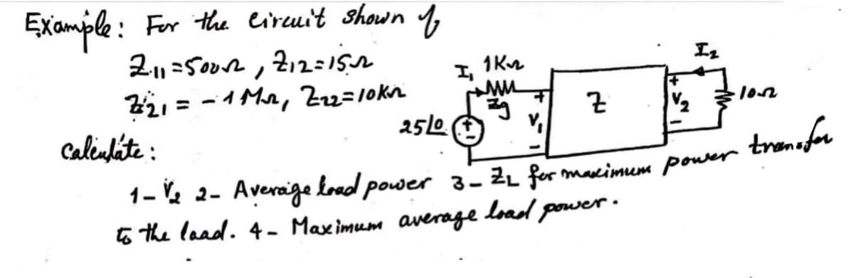
Q: to the Passive RLC Filter Shown R= 1500, L=22mH and c= 0.56nt, Determine the Following WO (6) Q A…
A:
Q: For the energy conversion system shown in Fig., if the airgap length is reduced from x = 0.05 to…
A: In the given question we need to discuss about the effect of reducing the air gap length.
Q: Assume an ideal-offset model for the diode with VON = 1 V. = Given Is 2 mA and R = = 1 k, find the…
A: The resistor, The source current, Diode voltage,
Q: Question 1: In Figure 1, what is the peak output voltage if the diodes are silicon? Determine…
A: Given:A rectifier circuit with silicon diodes,we need to find:peak output voltageDC (average value)…
Q: Complete the wave diagram for the flip-flop described by the following symbol: of Ꭰ st S R of SDCR…
A: Final answers are given belowExplanation:Step 1: Step 2: Step 3: Step 4:
Q: Using the ideal diode model, find the output voltage for the input voltage of the following circuit…
A: In the given questions we need to plot the output voltage waveform.
Q: Order the assumptions and steps according to the sequence used to derive the ideal diffusion current…
A: The first step in deriving the ideal diffusion current density of a p-n junction is to consider the…
Q: *4.32 For the circuit shown in Fig. P4.32, determine (a) H(s) = Vo/Vs and (b) h(t) given that R₁ =…
A: Please see the attached image for the answer.Explanation:
Q: 2) Determine whether the following system is time invariant using a graphical check. y(t) = x(t) +2
A: Given:whether the above system is time invariant?
Q: A power system consists 200 buses out of which 15 buses are generator bus, 10 buses are the reactive…
A:
Q: In the ideal Transformer given below find the power absorbed by the load. Primary and secondary…
A: The given data is shown below:
Q: VE 6.2 6.51 The transistor in the circuit of Fig. P6.51 has a very high ẞ. Find VE and Vc for VB (a)…
A:
Q: Consider the following state-space representation 0 1 0 x(t) = 0 0 1 x(t) + u(t) -18 -21 -8] မာ y(t)…
A: The objective of the question is to convert the given state-space representation into Jordan…
Q: What should be the voltage across the 3H inductor in the below given electrical circuit if the 5V…
A: The given data is shown below:
Q: A new model of electric vehicle contains two essential electronic components. Ifeither one of the…
A: The objective of the question is to find the probability density function (pdf) and the expected…
Q: 3. For a first-order system, we can measure its magnitude ratio and phase lag for varying AC…
A: In many engineering and scientific applications, understanding the time response of a system to a…
Q: A salient - pole 3 phase cylindrical synchronous machine has a direct-axis reactance equal to two…
A: This is a synchronous machine
Q: A pumped storage facility has a head of 450m and efficiency of 93%. What is the flow rate needed to…
A: The objective of this question is to calculate the flow rate needed to generate 100MW for 3.5 hours…
Q: H.W: Derive the following with drawing the circuit. ⚫The output voltage of the integrator Op-Amp.…
A: In the given questions we need to derive the output voltage of integrator and differentiator.
Q: (1) Consider the circuit shown in Fig. 1, where R₁ = R2 = 1 kn, R3 = 2 kN, V₁ = 12 V, and L = 10 H.…
A: The circuit diagram is shown below,where,
Q: A power system consists of 400 buses out of which 30 buses are generator bus. 40 buses are the ones…
A: In the given questions we need to calculate the size of jacobian matrix.
Q: Find: 11, 12 & 13
A:
Q: 1. Write the state-space matrix equations for the circuit shown. Use state variables x₁ = i(t) and…
A: The given circuit isThe state variables are⇒x1(t)=iL(t).⇒x2(t)=vC(t).The output is ⇒vo(t)=vC(t).We…
Q: Consider a system with frequency response of H (jw) jw+2 (jw+1)(jw+3) and suppose that the input to…
A: The given data is shown below:
Q: In the circuit shown the initial voltage on the capacitor is 72V positive at the lower terminal and…
A: In the given questions we need to calculate the output voltage.
Q: Thank you kindly. The follow-up question is "Find v(t) for t>0 in the circuit, using the Laplace…
A:
Q: Find v for t> 0, using Laplace equivalent circuits if v(0) = 8 V. Note: t>0 means that 10 V and 3 A…
A:
Q: 33. For the circuit of Figure 2.40, determine the circulating current and the voltages across each…
A: The circuit diagram is shown below,
Q: A rectangular toroid has 5000 turns and a self- inductance of 0.50 H. If the height is 0.20 m what…
A:

Step by step
Solved in 5 steps with 21 images


- I have just started my first Semester (Fall 2021) out of 4 semesters in Master of Applied Science (M.A.S) in Power Engineering at Illinois Institute of Technology. I did not clearly undersand the course enrollment system because I am new to the system, so I ended up enrolling in courses; ECE58-Microgrid Design and Operation, and ECE579-Computer Aided Design of Electrical Machines. It appears ECE582 listed ECE418 (Power System Analysis) as a prerequisite; and ECE539 requires ECE319 (Fundamentals of Power Engineering) and ECE412(Hybrid Electric Vehicle Drives) as prerequisites. Let me hasten to add that I graduated in 2009 in a different academic setup in Africa in Electrical Engineering. So, not only do I have to cover the gap of about 12 year out of classroom, but I have compounded the problem by jumping into advanced courses before enrolling into foundation courses. Unfortunately I can no longer switch courses as the enrollment window has passed. I am only left with one option; to…Explain the concept of FACTS (Flexible Alternating Current Transmission Systems) devices. How do they enhance the control and stability of power systems? Provide examples of FACTS devices and their applications.Show the derivation of the formula in transforming Delta (or Pi ) Network to Wye (or T) Network and vice-versa.
- Consider the load convention that is used for the RLC elements shown in Figure 2.2 of the text. A. If one says that an inductor absorbs zero real power and positive reactive power. is it (a) True (b) False B. If one says that a capacitor absorbs zero real power and negative reactive power (or delivers positive reactive power), is it (a) False (b) True C. If one says that a (positive-valued) resistor absorbs (positive) real power and zero reactive power, is it (a) True (b) FalseTOPIC: Power Systems, Power Plants & IlluminationINSTRUCTIONS:- Answer in this format: Given, Illustration, Required Conversion, Solution, Final Answer.- Step-by-step solution, do not skip even simple calculations to avoid confusion.- If answered in written form, make sure it is readable.PROBLEM: A generating station has two 50 MW units each running for 8,500 hours in a year and one 30 MW unit running for 1,250 hours in one year. The station output is 650 x 106 kWh per year. Calculate the utilization factor. 0.732 0.653 0.811 0.795You are given five light bulbs designed to operate on 160 mA current at 3.0 V (rms values), arid want to connect them in parallel, through an ideal transformer, to 120 V rms AC household power. a) Draw a circuit diagram showing the AC power source (a generator symbol ), the transformer, and resistors for the light bulbs. b) Is the required transformer step-up or step-down? What turns ratio N5/N is needed? e) Calculate the ruts current through both the primary and secondary coils of the trans former, in mA.
- The currents in each branch of a two - branched parallel circuit are given by expression i1 = 7.07sin(314t - π/4) A and i2 = 21.2sin((314t - π/3) A. The supply voltage is given by the expression v = 354sin 314t V. Determine the impedance Z1 and Z2. a. Z1 = 50.07 Ω, Z2 = 16.7 Ω b. Z1 = 35.4 Ω, Z2 = 8.35 Ω c. Z1 = 10.0 Ω, Z2 = 10.2 Ω d. Z1 = 14.46 Ω, Z2 = 14.14 ΩAs shown in the Figure , an external load resistor, R, is connected across the terminal a-b of the DC circuit. Based on Norton’s Theorem, calculate and analyse the circuit shown in the figure ( given V1=60V, V2=20V, R1 = 22ohm, R2 = 34ohm, R3 = 35ohm, R4 = 42ohm,) find R if i =0.5. What is the practical range of current i and value of R?. Kindly modify the circuit by changing only one of the parameters (either voltage or resistor value) so that i = 0.3 A.Q4. Economic analysis of the electricity market is an essential part of the operation of modern power systems. (A) The concepts of economic dispatch, load flow and optimal power flow are widely used in power system analysis. Define the optimal power flow problem and discuss how it differs from load flow and economic dispatch problems. Discuss the likely impact of the rapid adoption of renewables on the optimal power flow problem.
- Electric Machine-check image, all question there. Consider the above equivalent circuit of IM. A three phase, Y connected , 215 V (line to line), 7.5Kw , 60Hz , three pole IM has the following parameter values in Ω/phase referred to the stator R1=0.294Ω , R2=0.144 Ω, X1=0.203 Ω, X2=0.409 Ω, Xm=10.25 Ω The total friction , windage and core losses may be assumed to be constant at 350W independent of load, For a slip s=0.02, compute the followings a)Stator current b)Power factor(pf) c)Rotor speed d)Power Output(shaft) e)Output(shaft) torque f)Efficiency1. Thyristor-Controlled Series Capacitor (TCSC) for power factorimprovement2. What are the constraints are followed in Unit commitment?A hydro-electrie station is operated with a mean head (h) of 30 m and consume (discharge water) 218.75 * 10 6 m3 of water in one ycar for the average load. The expected load factor for the station is 80 %. Calculate the power in Kw for which the station should be designed (max.load). Assume that the mechanical efficiency of the turbine is 90% and the efficiency of the generator is 95%,