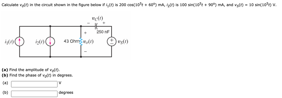
Calculate vo(t) in the circuit shown in the figure below if i, (t) is 200 cos(10°t + 60°) mA, i2(t) is 100 sin(105t + 90°) mA, and vs(t) = 10 sin(105t) V. vɖt) + 250 nF ij(1) i2(1) 43 Ohms vo(t) + vs(t) (a) Find the amplitude of vo(t). (b) Find the phase of vo(t) in degrees. (a) V (b) degrees
Q: For the signals provided below a. Which are periodic? Give their periods. b. Which are power…
A: The signal is said to be periodic if it repeats the output after some equal time interval. The power…
Q: Given the graph of the cosine function f (x) = cos x, evaluate the following limits: 27 37 1. lim…
A:
Q: t= 0 i(t) R 20 t= 20ms L Vbat 10V v(1) 400mH
A:
Q: An alternating current in a 4G signal transmitter is expressed as I = 5 sin(120nt + 0.52), I in mA,…
A: We are authorized to answer first three parts only. As you have not mentioned which part to answer.…
Q: For the circuit shown ,if the switch on at t=0, determine Vr, ir and vz as a function of time Ro
A: This circuit has a switch and is opened for a long time. It will close at time t=0. a) t=0, (t<0)…
Q: Given the circuit below. i, (t) = v210 cos(377t). Give your answer in four decimal places if it is…
A: As per our guide lines when student post question with multiple subparts we have to solve first…
Q: Q1: Fill all the blanks: 1- The total apparent power..... . 2- The capacitive network have a…
A: As per our guidelines we are supposed to answer only 3 sub part of a given question. Kindly repost…
Q: 10 2 ww The circuit in Fig. 8.12 has reached steady state at † = 0-. If the make- before-break…
A: Given : In the given circuit they have mentioned a second order system which is made up of capacitor…
Q: Example (1): For the circuit shown in figure (1), a 90 Q resistor, an 32 mH inductor and an 5 µF…
A: (a) The voltage in polar form is: The frequency of the source (ω) is 5000 Hz. The resistance (R),…
Q: Suppose an electrical signal generated, y(t) can be modelled as follows where t, is time in second,…
A: Given the output signal as given below: y(t)=0.5+2sin360πt-π4+1.5sin440πt+π2+sin1500t+π3 a) We need…
Q: Irwin, Engineering Circuit Analysis, 11e ISV 8.58 Find the current i, in the following circuit. 12 V…
A: Use superposition theorem to find out the current, Consider 5 V source first, remove other sources,…
Q: 2. a) Determine whether the following systems are (i) Stable/Unstable, (i) Causal/Noncausal, (iii)…
A: a..>> y(t)=ex(t) This function will give exponential output. And exponential function gives…
Q: The phase angle between the input waveform and the capacitor can then be measured using the…
A:
Q: 1. Given the sinusoidal voltage v (t) = 50 cos (30t + 10°) Volts, find: (a) The amplitude Vm, (b)…
A:
Q: 8.3.7 For the RLC circuit shown in the image below, if R1 = 5 2 and R2 = 6 2, C = 0.16 F, and the…
A:
Q: 2) For the circuit shown in Figure 2.1 below, if the input is excited by a square wave voltage…
A:
Q: Question 2: The temperature of an object changes with time and this change is in simple harmonic…
A:
Q: For each of the following characteristic equations, a) Sketch the root locus plot for 0 < K< b) Find…
A: "Since you have posted a question with multiple sub parts we will solve first three subpart for you…
Q: 4. Determine the magnitude of the following instantaneous equations (answers must be in 3 decimal…
A: Here instantaneous equations is given ,we have to calculate particular time value(magnitude) by…
Q: For the circuit shown ,if the switch on at t=0 , determine Vr, ir and vz as a function of time Ro
A:
Q: Ex. 900. x(t)= CO + C1*sin(w*t+theta1) + C2*sin(2*w*t+theta2) x(t)= A0 + A1*cos(w*t) + B1*sin(w*t) +…
A:
Q: g(1) = 20cos (40at – ) Identify the even and odd parts of g(0. Multiple Choice The even part of the…
A: even part of the signal x(t) = x(t) +x(-t)2 odd part of the signal x(t) = x(t) -x(-t)2 First we will…
Q: 24. In time domain represenatation of a signal, a signal with an expression of 220 cos (377t -90) is…
A:
Q: QUESTION 2 io + 10 cos 21 V C 6 sin 2t V For the circuit shown above, what is the amplitude of the…
A:
Q: The voltage wave propagating on a transmission line is given in real space-time form as v(z, t) =…
A:
Q: 32. A time domain circuit with v(t) = 100 sin(377t) in 5mS, what is the effective current if the…
A: 32. v(t) = 100 sin(377t) v(t) = vm sin(wt) Where vm = 100 v Load R = 10 ohm Vrms = 0.707 vm =…
Q: 1. The current source in the circuit shown below is generating a sinusoidal waveform such that iç…
A: By using current division rule we can find current in second branch then by using ohm's law we can…
Q: 1 mH 11. Given that i,()-5 cos(or+120) and 4,(1) = 5cos(ox +60) hoad() 50 2: find f) (in Amperes) in…
A: The circuit is provided as:
Q: 9. In the non-sinusoidal periodic current circuit shown in Fig. 9, R=20SN, L=20mH, 50 G = 50µF, C,…
A: Periodic Signal: A signal x(t) is said to be periodic if it repeats itself after finite amount of…
Q: 12.26 In the circuit shown in Fig. 12.16, the dc current source is replaced with a sinusoidal source…
A:
Q: Unanswered Question 2 What is the RMS value of x(t)? A signal x(t) has a period of 2 sec and is…
A: We have to find rms of x(t)
Q: 1) Given the sinusoidal voltage v(t) = 50 cos(30t + 10°) V, find: (a) the amplituc (c) the frequency…
A:
Q: Multiples of 360° may be added to or subtracted from the argument of any sinusoidal function without…
A: According to question we discuss about A1.
Q: The circuit of Fig. 1.100 has the following data: E = 150 V, L = 10 mH rL (resistance of the…
A:
Q: Let vj = 8 sin 100rt and vz = 6 sin 99tt. Show that v= vj + vz is periodic. Find the period, and the…
A: As per our guidelines we are supposed to answer?️ only one question. Kindly repost other questions…
Q: B: Find the waveform of the voltage V(t) in the circuit shown below given that: e(t)-2.5 sin(500t)…
A: The circuit is as shown below, Given, e(t) = 2.5sin(500t), i(t) = 1.414cos(1000t),
Q: The reciprocal current is denoted by i = 100 in (314 t + 30°). Then its (1) maximum value (2)…
A:
Q: Electrical Engineering A four-element array of isotropic sources is placed along the z-axis. The…
A:
Q: Calculate vo(t) in the circuit shown in the figure below if i,(t) is 200 cos(10°t + 60°) mA, i2(t)…
A: Write the expression for the current I1, I2, and reactance of the capacitor Xc in the form of…
Q: x(t)= C0 + C1*sin(w*t+theta1) + C2*sin(2*w*t+theta2) x(t)= A0 + A1*cos(w*t) + B1*sin(w*t) +…
A:
Q: Example A series AC circuit is shown in Fig. 8. Calculate the source current, apparent, real and…
A: Given circuit shown with v(t)=16sin10t+25° v
Q: need the correct solve asap plz
A:
Q: The current in an L-R-C series circuit has amplitude 0.120 Aand angular frequency 8.00 * 103 rad/s,…
A: It is given that:
Q: SYSTEM CONTROLLER R(s) +, Y (s) 2s + 2 C(s) s(s + 5)(s – 2) Consider the system below. For this…
A:
Q: 10 + /s(+ 1 F F = v(t) 1 H ?For the circuit shown above, what is the amplitude of the voltage v(t)…
A:
Q: Question 2 What is the RMS value of x(t)? A signal x(t) has a period of 1 sec and is given as 1 x(t)…
A: A simple problem on RMS value finding.Look below for solution:-
Q: Example 9.7 • The sinusoidal current source in the circuit shown in Fig. 9.18 produces the current…
A: To write the the frequency domain equivalent of the given circuit we must replace capacitor and…
Q: The phasor current I, is 5445° A. 1. Find Ia. Ies and Vg. 2. If w = 800 rads/s, write the…
A:
Q: The voltage wave propagating on a transmission line is given in real space-time form as v(z, t) =…
A:
Step by step
Solved in 4 steps with 4 images
- 32. A time domain circuit with v(t) = 100 sin(377t) in 5mS, what is the effective current if the load is 10 ohms? 6.14A 8.67A 7.07A 10A 36. In a series RL circuit, if cos θ = 0.707, the voltage ________ the current by _______. leads, 90 degrees lags, 90 degrees leads, 45 degrees lags, 45 degrees 37. What will happen when an ideal capacitor was installed in parallel with the load? system power factor decreases system power factor increases system will be under voltage system power loss increases 39. Phase angle in a balance circuit has a difference of __________ degrees. 60 90 30 120A 40 Ω resistor and a 50 μ F capacitor are connected in series and supplied with analternating voltage v = 283 sin 314 t. The supply is switched on at the instant when the voltageis zero. Determine the expression for the instantaneous current at time t.x(t)= C0 + C1*sin(w*t+theta1) + C2*sin(2*w*t+theta2) x(t)= A0 + A1*cos(w*t) + B1*sin(w*t) + A2*cos(2*w*t) + B2*sin(2*w*t) A0=-1, A1= 5, B1= 6, A2=-3, B2= 4, w=500 rad/sec. Express all angles between plus and minus 180 degrees. Determine C0, C1, theta1 (deg), C2, theta2 (deg)
- In the circuit shown below, the switch is connected to the battery at t = 0 and returns to potential of earth at t = 20 ms. Determine:a)The expression of the input voltage in the time and frequency domain, v(t) and V(s).b)The circuit impedance Z(s) = V(s)/I(s).c)The current expression, i(t).The current in an L-R-C series circuit has amplitude 0.120 Aand angular frequency 8.00 * 103 rad/s, and it has its maximum positivevalue at t = 0. The resistance is 95.0 Ω, the inductance is 6.50 mH,and the capacitance is 0.440 mF. For the resistor, inductor, and capacitor,find (a) the voltage amplitudes and (b) the instantaneous voltages att = 0.305 ms.The phasor current Ib in the circuit is 25 0 . mA.1. Find Ia, Ic, and Ig.2. If ω=1500 rad/s, write expressions for ia(t), ic(t), and ig(t).
- A chirp is a signal of the form x(t) = A sin(2πϕ(t)) where A is the amplitude and the function ϕ(t) is the phase of the chirp. If the phase has the form ϕ(t) = f0 ((t1 − t0) / ln ( f1/ f0 )) * ((f1/ f0)^( t−t0/ t1−t0 ) − 1 ) + ϕ0, Then the signal is called a logarithmic chirp, exponential chirp, or exponentially swept sine. Here, f0 is the frequency at time t0, f1 is the frequency at time t1, and ϕ0 is the phase at time t0, where t1 > t0, f1 ̸= f0, and f1f0 > 0 The frequency of a chirp at time t is f(t) = dϕ/ dt . What would the frequency of a logarithmic chirp as a function of time t and show that the frequency strictly increases for t0 < t < t1 when f1 > f0 and strictly decreases for t0 < t < t1 when f1 < f0.? Thank you for the help.Suppose an electrical signal generated, y(t) can be modelled as follows where t, is time in second, y(t) is voltage in mv. a) Produce graphs showing the amplitude and phase spectrum of y(t). b) State whether this time-domain signal y(t) is periodical, or non-periodical and justify your answer.Communication system Let's consider a communication system where four signals with different frequencies f1, f2, f3, and f4) are combined to form a single composite signal. The composite signal is represented by the equation: s(t) = 3 sin(500m (k, x t) + T/6) + 4 sin (10007 (kz × t) + T/4) + 2 sin(1500t (k3 X t) + T/3) + 5 sin(2000m(k. X t) + /2) Given the scaling factors: kg = 0.8, kz = 1.6, k3 = 2.4, and k4 = 3.2. Determine the fundamental frequency
- Obtain the value of I1, if M=1/√2H, and the circuit is in steady state at t = 0.Assume that the voltage drop across the resistor, ER, is 78 V, that the voltage drop across the inductor, EL, is 104 V, and the circuit has a total impedance, Z, of 20 . The frequency of the AC voltage is 60 Hz. ETITZ20VAPFER78VIRRPEL104VILXLVARsLLHomework: For the circuit shown Find the mathematical expression for the transient behaviour of the V C and ic if the capacitor was initially uncharged and the switch is closed at position 1 when 1. 2. 3. t = 0 sec. Find the mathematical expression for V C and ic if the switch is moved to position . 2att - 1 Plot the waveforms of the V C and i C obtained from the parts 1 to 3. i C; 10mu 4 mA R 1 * 5k * Omega C R 2; 1k * Omega; R 3 3 kΩ in the figure below: