Examine the circuits shown below for each half cycle. On each circuit indicate clearly which diode is on and show the path & direction of the currents. Use 2nd approximation for the diodes. a) What type of circuit is this? b) What is the total peak secondary voltage? c) Find the peak voltage across each half of the secondary (Circuit #1). d) Sketch the voltage waveform across R₁. e) What is the peak current through each diode? f) What is the PIV (peak inverse voltage) for each diode? Circuit #1 Circuit #2 120 V eeeee relese LOLD WI R₁ LOAD N A 120 V M 120 Va elese 00000 LOWD ww LOKO
Examine the circuits shown below for each half cycle. On each circuit indicate clearly which diode is on and show the path & direction of the currents. Use 2nd approximation for the diodes. a) What type of circuit is this? b) What is the total peak secondary voltage? c) Find the peak voltage across each half of the secondary (Circuit #1). d) Sketch the voltage waveform across R₁. e) What is the peak current through each diode? f) What is the PIV (peak inverse voltage) for each diode? Circuit #1 Circuit #2 120 V eeeee relese LOLD WI R₁ LOAD N A 120 V M 120 Va elese 00000 LOWD ww LOKO

Chapter59: Motor Startup And Troubleshooting Basics
Section: Chapter Questions
Problem 12SQ: How is a solid-state diode tested? Explain.

Related questions
Question
Transcribed Image Text:0-
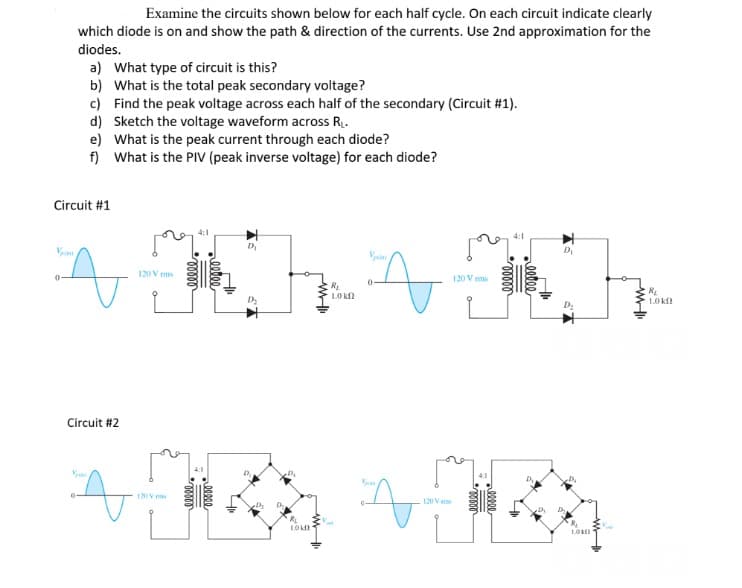
Examine the circuits shown below for each half cycle. On each circuit indicate clearly
which diode is on and show the path & direction of the currents. Use 2nd approximation for the
diodes.
a) What type of circuit is this?
b) What is the total peak secondary voltage?
c) Find the peak voltage across each half of the secondary (Circuit #1).
d) Sketch the voltage waveform across R₁.
Circuit #1
0
e) What is the peak current through each diode?
f)
What is the PIV (peak inverse voltage) for each diode?
Circuit #2
120 Vrms
4:1
M:
120 V ms
00000
00000
D₁
LOKO
R₁
10 k
Vp
120 V
pe
120 V mms
100000
D₂
D₂
D₁
D₂
D₂
LORE
R₁
1.0 k
Expert Solution
This question has been solved!
Explore an expertly crafted, step-by-step solution for a thorough understanding of key concepts.

Step by step
Solved in 3 steps with 1 images

Knowledge Booster


Learn more about
Need a deep-dive on the concept behind this application? Look no further. Learn more about this topic, electrical-engineering and related others by exploring similar questions and additional content below.Recommended textbooks for you

Delmar's Standard Textbook Of Electricity
Electrical Engineering
ISBN:
9781337900348
Author:
Stephen L. Herman
Publisher:
Cengage Learning
Delmar's Standard Textbook Of Electricity
Electrical Engineering
ISBN:
9781337900348
Author:
Stephen L. Herman
Publisher:
Cengage Learning