Example 4.11 Find the Norton equivalent circuit of the circuit in Fig. 4.39 at terminals a-b. 8Ω ww Solution: We find Ry in the same way we find RTh in the Thevenin equivalent circuit. Set the independent sources equal to zero. This leads to the circuit in Fig. 4.40(a), from which we find RN. Thus, 2 A 5Ω 12 V 20 X 5 5 || (8 + 4 + 8) = 5 || 20 = = 4 2 25 8Ω RN = Figure 4.39 For Example 4.11. To find Iy, we short-circuit terminals a and b, as shown in Fig. 4.40(b). We ignore the 5.0 resistor because it has been short.circuited
Example 4.11 Find the Norton equivalent circuit of the circuit in Fig. 4.39 at terminals a-b. 8Ω ww Solution: We find Ry in the same way we find RTh in the Thevenin equivalent circuit. Set the independent sources equal to zero. This leads to the circuit in Fig. 4.40(a), from which we find RN. Thus, 2 A 5Ω 12 V 20 X 5 5 || (8 + 4 + 8) = 5 || 20 = = 4 2 25 8Ω RN = Figure 4.39 For Example 4.11. To find Iy, we short-circuit terminals a and b, as shown in Fig. 4.40(b). We ignore the 5.0 resistor because it has been short.circuited

Introductory Circuit Analysis (13th Edition)
13th Edition
ISBN:9780133923605
Author:Robert L. Boylestad
Publisher:Robert L. Boylestad
Chapter1: Introduction
Section: Chapter Questions
Problem 1P: Visit your local library (at school or home) and describe the extent to which it provides literature...

Related questions

Question
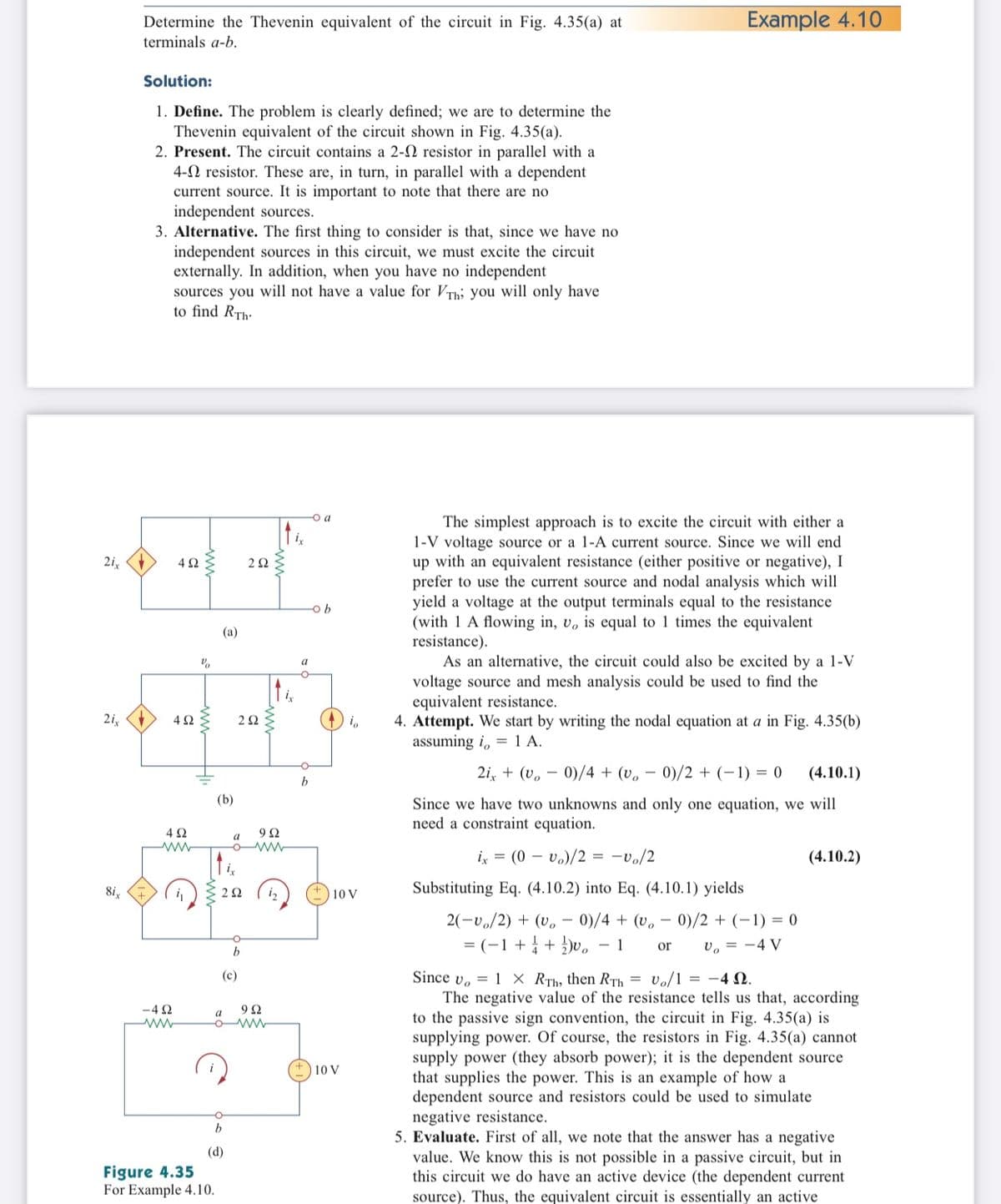
Transcribed Image Text:Determine the Thevenin equivalent of the circuit in Fig. 4.35(a) at
Example 4.10
terminals a-b.
Solution:
1. Define. The problem is clearly defined; we are to determine the
Thevenin equivalent of the circuit shown in Fig. 4.35(a).
2. Present. The circuit contains a 2-2 resistor in parallel with a
4-N resistor. These are, in turn, in parallel with a dependent
current source. It is important to note that there are no
independent sources.
3. Alternative. The first thing to consider is that, since we have no
independent sources in this circuit, we must excite the circuit
externally. In addition, when you have no independent
sources you will not have a value for VTh; you will only have
to find RTh-
-o a
The simplest approach is to excite the circuit with either a
1-V voltage source or a 1-A current source. Since we will end
up with an equivalent resistance (either positive or negative), I
prefer to use the current source and nodal analysis which will
yield a voltage at the output terminals equal to the resistance
(with 1 A flowing in, v, is equal to 1 times the equivalent
resistance).
As an alternative, the circuit could also be excited by a 1-V
voltage source and mesh analysis could be used to find the
equivalent resistance.
4. Attempt. We start by writing the nodal equation at a in Fig. 4.35(b)
assuming i, = 1 A.
2i,
4Ω
(a)
a
2i,
2 2
2i, + (v, – 0)/4 + (v.
0)/2 + (-1) = 0
(4.10.1)
b
(b)
Since we have two unknowns and only one equation, we will
need a constraint equation.
4Ω
9Ω
a
ix = (0 – vo)/2 = -vo/2
(4.10.2)
i,
8i,
C 22
i2
Substituting Eq. (4.10.2) into Eq. (4.10.1) yields
10 V
2(-v./2) + (v.
0)/4 + (v, – 0)/2 + (-1) = 0
= (-1+ + )v,
- 1
v, = -4 V
or
b
Since v. = 1 × RTh, then RTh = Vo/1 = -4 N.
The negative value of the resistance tells us that, according
to the passive sign convention, the circuit in Fig. 4.35(a) is
supplying power. Of course, the resistors in Fig. 4.35(a) cannot
supply power (they absorb power); it is the dependent source
that supplies the power. This is an example of how a
dependent source and resistors could be used to simulate
negative resistance.
5. Evaluate. First of all, we note that the answer has a negative
value. We know this is not possible in a passive circuit, but in
this circuit we do have an active device (the dependent current
(c)
-4 2
9Ω
a
10 V
(d)
Figure 4.35
For Example 4.10.
source). Thus, the equivalent circuit is essentially an active
ww
ww
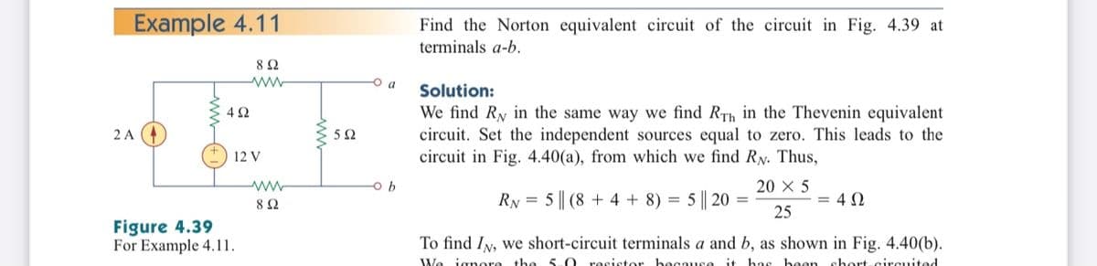
Transcribed Image Text:Example 4.11
Find the Norton equivalent circuit of the circuit in Fig. 4.39 at
terminals a-b.
8Ω
O a
Solution:
We find Ry in the same way we find RTh in the Thevenin equivalent
circuit. Set the independent sources equal to zero. This leads to the
circuit in Fig. 4.40(a), from which we find RN. Thus,
2 A
5Ω
12 V
ww
20 X 5
RN = 5 || (8 + 4 + 8) = 5 || 20 =
25
= 4 0
Figure 4.39
For Example 4.11.
To find IN, we short-circuit terminals a and b, as shown in Fig. 4.40(b).
We ignore the 5-0 resistor because it has been short-circuited
Expert Solution
This question has been solved!
Explore an expertly crafted, step-by-step solution for a thorough understanding of key concepts.

This is a popular solution!

Trending now
This is a popular solution!

Step by step
Solved in 2 steps with 5 images

Knowledge Booster


Learn more about
Need a deep-dive on the concept behind this application? Look no further. Learn more about this topic, electrical-engineering and related others by exploring similar questions and additional content below.Recommended textbooks for you
Introductory Circuit Analysis (13th Edition)
Electrical Engineering
ISBN:
9780133923605
Author:
Robert L. Boylestad
Publisher:
PEARSON

Delmar's Standard Textbook Of Electricity
Electrical Engineering
ISBN:
9781337900348
Author:
Stephen L. Herman
Publisher:
Cengage Learning

Programmable Logic Controllers
Electrical Engineering
ISBN:
9780073373843
Author:
Frank D. Petruzella
Publisher:
McGraw-Hill Education
Introductory Circuit Analysis (13th Edition)
Electrical Engineering
ISBN:
9780133923605
Author:
Robert L. Boylestad
Publisher:
PEARSON
Delmar's Standard Textbook Of Electricity
Electrical Engineering
ISBN:
9781337900348
Author:
Stephen L. Herman
Publisher:
Cengage Learning
Programmable Logic Controllers
Electrical Engineering
ISBN:
9780073373843
Author:
Frank D. Petruzella
Publisher:
McGraw-Hill Education

Fundamentals of Electric Circuits
Electrical Engineering
ISBN:
9780078028229
Author:
Charles K Alexander, Matthew Sadiku
Publisher:
McGraw-Hill Education

Electric Circuits. (11th Edition)
Electrical Engineering
ISBN:
9780134746968
Author:
James W. Nilsson, Susan Riedel
Publisher:
PEARSON

Engineering Electromagnetics
Electrical Engineering
ISBN:
9780078028151
Author:
Hayt, William H. (william Hart), Jr, BUCK, John A.
Publisher:
Mcgraw-hill Education,