Example Use the superposition theorem to find v in the circuit of Fig. 4.6. 8Ω Solution: Since there are two sources, let 6 V 4Ω 43 A v = U1 + 2
Example Use the superposition theorem to find v in the circuit of Fig. 4.6. 8Ω Solution: Since there are two sources, let 6 V 4Ω 43 A v = U1 + 2

Introductory Circuit Analysis (13th Edition)
13th Edition
ISBN:9780133923605
Author:Robert L. Boylestad
Publisher:Robert L. Boylestad
Chapter1: Introduction
Section: Chapter Questions
Problem 1P: Visit your local library (at school or home) and describe the extent to which it provides literature...

Related questions

Question
Superposition:
Hi, can you find "v" using superposition with mesh analysis only? No current and voltage division please.
Transcribed Image Text:Keep in mind that superposition is based 8R
reason, it is not applicable to the effect on power due to each source,
because the power absorbed by a resistor depends on the squ'are of
the voltage or current. If the power value is needed, the current
through (or voltage across) the element must be calculated first using
superposition.
Example 4.3
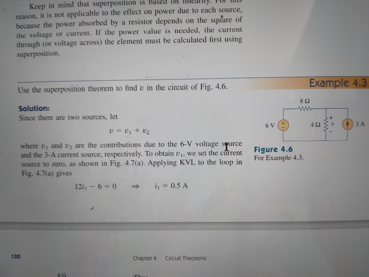
Use the superposition theorem to find v in the circuit of Fig. 4.6.
82
Solution:
Since there are two sources, let
6 V
4Ω
3 A
v = U, + V2
where v and vz are the contributions due to the 6-V voltage syurce
and the 3-A current source, respectively. To obtain v,, we set the current
source to zero, as shown in Fig. 4.7(a). Applying KVL to the loop in
Fig. 4.7(a) gives
Figure 4.6
For Example 4.3.
12i, - 6 = 0
i = 0.5 A
132
Chapter 4
Circuit Theorems
89
TI
Expert Solution
This question has been solved!
Explore an expertly crafted, step-by-step solution for a thorough understanding of key concepts.

Step by step
Solved in 3 steps with 2 images

Knowledge Booster


Learn more about
Need a deep-dive on the concept behind this application? Look no further. Learn more about this topic, electrical-engineering and related others by exploring similar questions and additional content below.Recommended textbooks for you
Introductory Circuit Analysis (13th Edition)
Electrical Engineering
ISBN:
9780133923605
Author:
Robert L. Boylestad
Publisher:
PEARSON

Delmar's Standard Textbook Of Electricity
Electrical Engineering
ISBN:
9781337900348
Author:
Stephen L. Herman
Publisher:
Cengage Learning

Programmable Logic Controllers
Electrical Engineering
ISBN:
9780073373843
Author:
Frank D. Petruzella
Publisher:
McGraw-Hill Education
Introductory Circuit Analysis (13th Edition)
Electrical Engineering
ISBN:
9780133923605
Author:
Robert L. Boylestad
Publisher:
PEARSON
Delmar's Standard Textbook Of Electricity
Electrical Engineering
ISBN:
9781337900348
Author:
Stephen L. Herman
Publisher:
Cengage Learning
Programmable Logic Controllers
Electrical Engineering
ISBN:
9780073373843
Author:
Frank D. Petruzella
Publisher:
McGraw-Hill Education

Fundamentals of Electric Circuits
Electrical Engineering
ISBN:
9780078028229
Author:
Charles K Alexander, Matthew Sadiku
Publisher:
McGraw-Hill Education

Electric Circuits. (11th Edition)
Electrical Engineering
ISBN:
9780134746968
Author:
James W. Nilsson, Susan Riedel
Publisher:
PEARSON

Engineering Electromagnetics
Electrical Engineering
ISBN:
9780078028151
Author:
Hayt, William H. (william Hart), Jr, BUCK, John A.
Publisher:
Mcgraw-hill Education,